Second life of an old radio
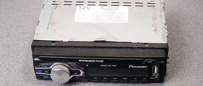
If you have a broken car radio, don't rush to throw it away. In skillful hands, it can find a new life and serve for a long time. Using the example of a faulty old “Pioneer 1091” type, we will tell you how to “pump” it.
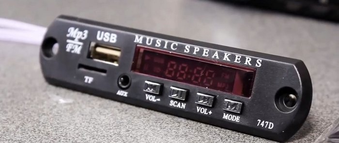
To restore we need an MP3 decoder. It should be purchased additionally. The Chinese have such a device on AliExpress that is relatively inexpensive - .
Let's upgrade the radio with an MP3 module
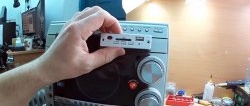
We purchased a simple decoder model with a minimum set of necessary functions: FM radio, playback from TF cards and USB flash drives, an AUX connector and the ability to connect external devices via Bluetooth.
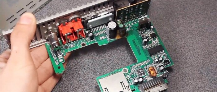
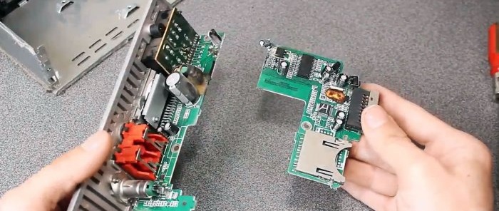
The electronic board of the radio can be divided into two parts: the sound amplifier and the control unit. The amplifier chip is usually located at the bottom and is mounted on a metal radiator.
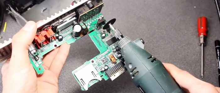
In order to prevent possible short circuits in the faulty control unit, we will exclude it from the circuit by carefully sawing it off. A burr machine with a cutting disc installed on it will help us with this.
Thus, we got two boards: one with an amplifier, the second with control controllers. We will use only the amplifier and replace the “brains” of the device.
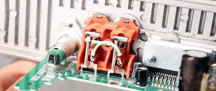
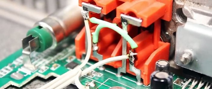
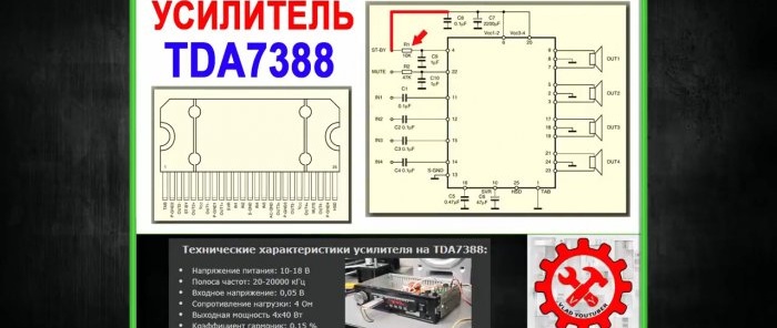
The TDA7378 amplifier chip is four-channel.The input signal to each of them is supplied through a separate tulip. Since the MP3 decoder has only 2 outputs, let's connect pairs of tulips in parallel.
We solder wires to the input connector of the tulips that will go to the output of the decoder.
We will cut off the “plus” power supply track, and solder two wires in its place. One of them will go to the switch, the second will be connected to the fuse.
The TDA7378 chip will not just start when power is applied to it. The fact is that the microcircuit has a standby mode. If a logical zero arrives at the fourth pin of the microcircuit (no power), then it goes into Stand-bay mode with low current consumption. To activate the operating mode, it is necessary to apply a logical one signal. It is impossible to supply 12V directly for this; the current should be limited to a resistance of 10 kOhm.
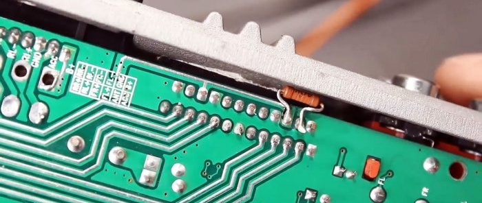
Let's connect the 4th and 6th legs of the microcircuit with a 10 kOhm resistor directly on the board.
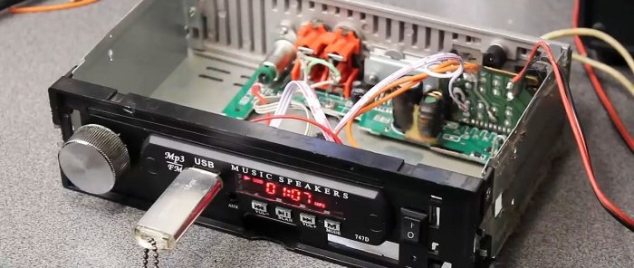
On the front wall of the radio we will make holes for the decoder, volume control potentiometer and switch key. Let's mount it all.
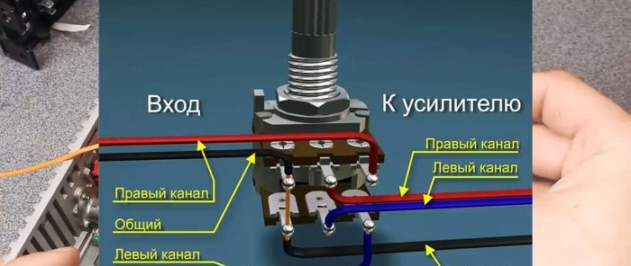
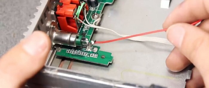
A stereo potentiometer is a construction resistor with a logarithmic dependence and a nominal value of 10-70 kOhm. We connect according to the following diagram:Let's disconnect the antenna socket, connecting instead to the corresponding wire of the decoder.
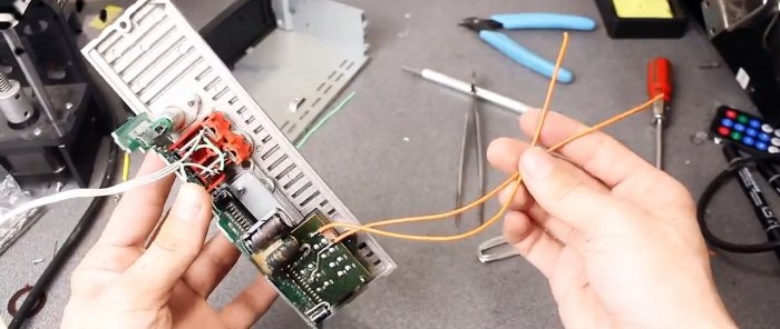
All that remains is to connect all the wires and assemble the device. You can supply 12 V power from any powerful power supply, for example, from a personal computer.
Of course, the appearance of the device was not impressive. However, this does not affect the functionality in any way: the circuit works as intended. In any case, this approach is much better. Instead of throwing away the radio, we gave it a second life.

