How to convert a printer unit into a universal power source
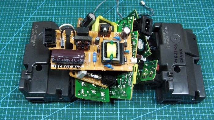
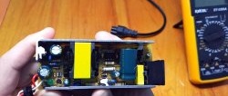
There was a need for a 15 volt power supply. I wanted to use a transformer with a rectifier. Connect a stabilizer to them. This design will not be small. I remembered. I have a large number of power supply MFPs and printers. The dimensions of the block are not large and the weight is also just right.
Scheme
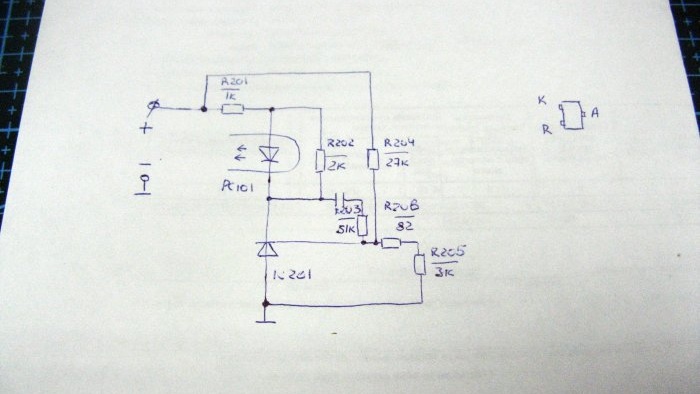
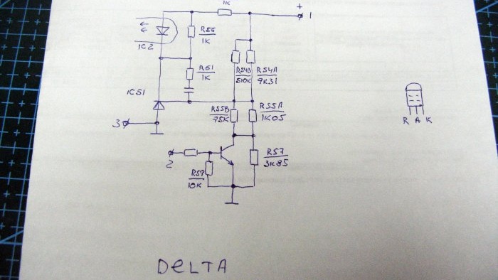
According to the scheme, these blocks are almost identical. There is no need to touch the network part. It is necessary to change the nominal value in the optocoupler harness. In almost all blocks the circuit has a TL431 stabilizer. Having studied its connection diagram, the modification becomes clear. I redrew part of the diagram.
First power supply: Second power supply:It has one more output contact. To start the unit you need to close contacts 1 and 2.
Remaking the printer power supply
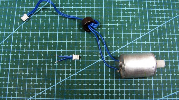
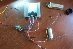
Let's focus on finalizing the first one. I made test leads from the same MFP. I will use the one with the motor.
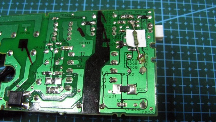
You need to remove resistor R204. Since we have it at 27 kOhm, we can take more. I found a 25 kOhm resistor.
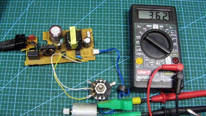
We turn the resistor slider and look at the adjustment range. My minimum is 3.6 volts. As a load, I connected a motor from the same MFP.
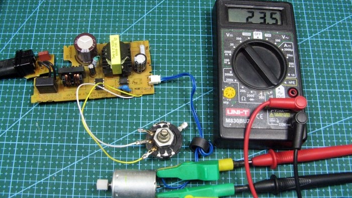
The maximum I got was 23.5 volts. This is the range of adjustment.
I'll turn it up to 15 volts. You need to measure the resistance of the resistor, for me it was 12 kOhm.
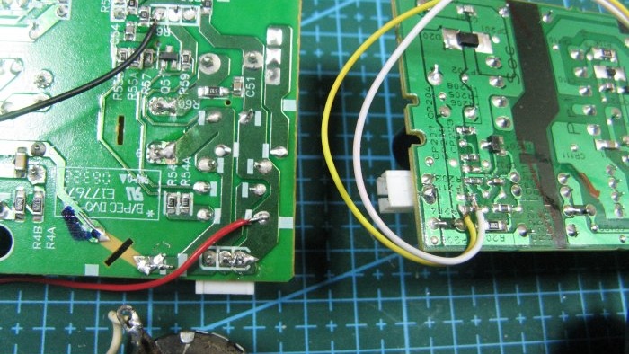
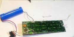
The second board is configured in a similar way. I will only show where the wires are soldered. You also need to unsolder the resistors from the positive. I have a jumper installed there, it needs to be removed.
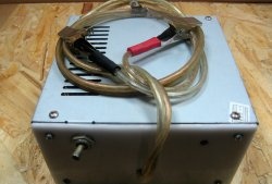
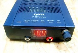
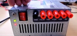
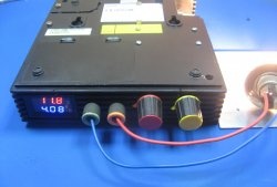
This is such a simple modification. This method can be used to modify almost any board. The stabilizer chip is the same, but in a different package. You can install an adjustment resistor. Install the board into a miniature case. Bring the resistor to the housing, equip it with a voltmeter and get an adjustable power supply. You can buy a non-working printer cheaply. Power supplies rarely fail.

