Step-down transformer 1978

Step-down transformer 1978
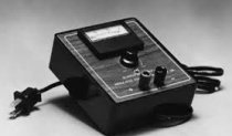
I found a 12 volt power supply at home that was used to charge batteries. He looks like this
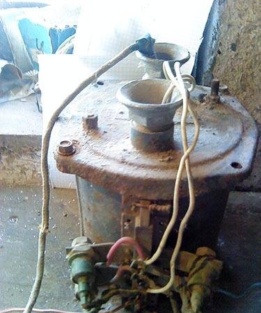
<
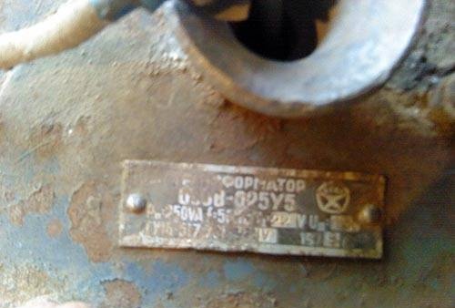
It consists of a step-down transformer and a diode bridge (matrix) that rectifies the alternating current coming from the transformer into direct current.
Let's start with it, it consists of four very powerful diodes, brand unknown, the only thing we could see was “Made in the USSR”; when there is a short circuit, the insulation on wires with a cross-section of 2 mm instantly melts, and the diodes are almost cold. Here they are close up
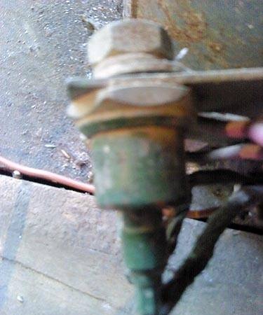
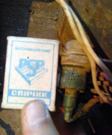
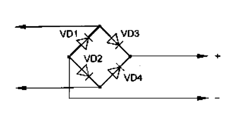
The diodes are connected according to a standard rectifier circuit
This is what it looks like in this case
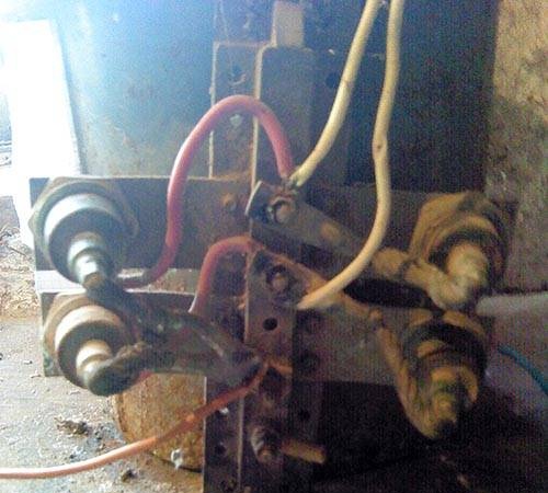
The connecting wires are used with a very large cross-section; all connections are made using bolts and nuts, otherwise, at high current, the insulation may ignite or the wires may simply melt.
Now let's move on to disassembling the compartment with the transformer, the top cover is held on by two bolts, unscrew it, remove the cover and take out the transformer itself
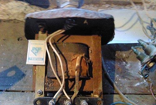
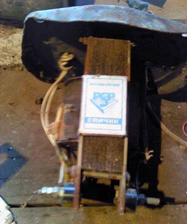
It, like any transformer of this type, has two windings, this is the primary winding to which 220 V is supplied and the secondary from which 12 V is removed
The primary winding consists of a copper wire with a cross-section of 1 mm; the mains voltage is connected directly to it
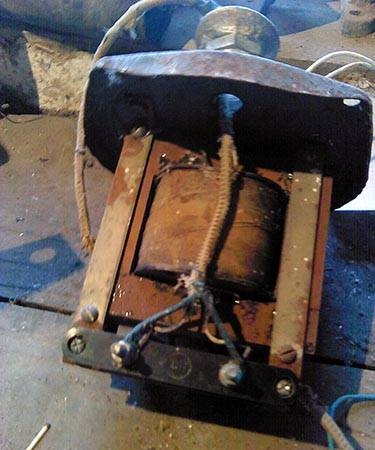
Now let's move on to the secondary winding at 12 V, here are the winding taps
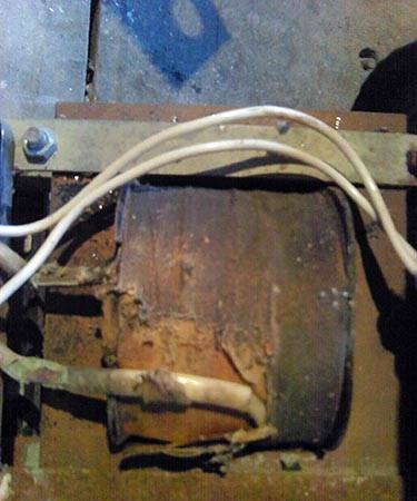
This winding no longer consists of wire, but of copper tape 1.5 mm thick and about 4 mm wide. Similar windings are used in welding machines, since the resistance of such a tape is low and hence the high current strength, I did not dare to measure it, in a similar situation I have already lost one ammeter per 20 amperes, and the tape because it takes up less volume compared to a cylindrical shape ordinary wire, since the cylinder has a smaller contact area.
Evidence of high current may be a short circuit response.

That's all we can do is be proud of the quality of the power supply, because it is now 32 years old, and it still continues to work properly.
Video of an attempt to short-circuit a transformer

come back
Comment
  • bowtiesmilelaughingblushsmileyrelaxed relaxedsmirk
    heart_eyeskissing_heartkissing_closed_eyesflushedrelievedsatisfiedgrin
    winkstuck_out_tongue_winking_eyestuck_out_tongue_closed_eyesgrinningkissingstuck_out_tonguesleeping
    worriedfrowninganguishedopen_mouthgrimacingconfusedhushed
    expressionlessunamusedsweat_smilesweatdisappointed_relievedwearypassive
    disappointedconfoundedfearfulcold_sweatperseverecrysob
    joyastonishedscreamtired_faceangryragetriumph
    sleepyyummasksunglassesdizzy_faceimpsmiling_imp
    neutral_faceno_mouthinnocent
3+three=
Comments (6)
  1. Danbaz
    #1 Danbaz Guests 26 September 2011 22:09
    3
    And what is this for? boast that there was such a Soviet miracle at home?
  2. Levsha
    #2 Levsha Guests 10 March 2012 17:39
    5
    This is how they did it in the Soviet years.
    good trans. You can make spot welding from it)))
  3. Sergey
    #3 Sergey Guests 13 May 2013 22:10
    3
    Funny post. )) To search with a screwdriver - disassemble the charger? Yeah, that's cool.
    But this doesn’t belong in the “Do it yourself” section, we need another “Break it yourself”. Well, as for the transformer, there’s practically nothing that gets spoiled there. We caught a huge Sovdepov welder from the lake with an adjustment knob, washed it, dried it, it works. It doesn't even penetrate the body.
  4. Stone
    #4 Stone Guests 22 November 2013 17:50
    3
    In principle, this is information for the future on how to squeeze out the maximum current in the smallest dimensions. So, thank you from me.
    Let's say I need to get an awesome current at the output at 1.5V. A large-diameter wire may not be able to be inserted into the trans without disassembling it, but a tape can be easily inserted.
  5. Nikolay
    #5 Nikolay Guests 1 May 2017 23:21
    2
    It is precisely these trances in the same housing that we use in our production as a portable source for carrying 12 volts. In photo 6 there are three bolts, one free. Through it, a fuse in the form of a bug wire is connected to the circuit break.
  6. student
    #6 student Guests December 8, 2017 21:20
    6
    10 ampere diodes from the series (V-10 voltage class). I installed these in a 50-amp power supply, had doubts, and screwed hefty radiators to them. With a current of 50-60 amperes from the bridge in 4 hours they heated up to about 40-45 degrees. Why? Yes, because without radiators the case would be 2 times smaller and lighter, and the unit works only 20 minutes a day. If you want to do anything with them, feel free to install them without a radiator; they will easily maintain the current rating.