LED color music
Sometimes you really want to create a bright light show at home, invite friends, turn up the music louder and plunge into the atmosphere of a disco. There are usually no problems with music and friends, but organizing color music can be quite problematic. Even the simplest lighting effects sometimes cost a lot of money, and besides, they are not sold in all stores. What to do if the desire to enjoy the lights blinking to the beat of the music does not fade away? There is a way out - to assemble the color music yourself.
Color music scheme
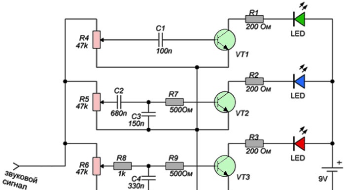
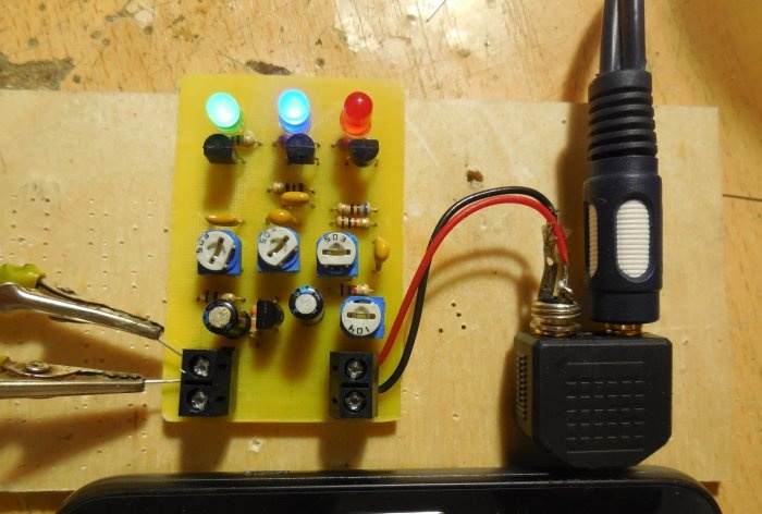
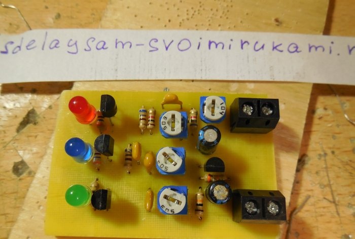
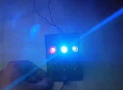
The circuit is as simple as boots, it contains only three transistors and a handful of resistors with capacitors. It contains three filters for low, medium and high frequencies, so this color music can be called three-channel. Red Light-emitting diode lights up when the audio signal is dominated by low frequencies, blue Light-emitting diode responds to mid frequencies, and green to high frequencies. Trimmer resistors R4 - R6 regulate the sensitivity of each channel, with their help the required brightness is set. Transistors VT1 – VT3 switch LEDs, here you can use any low-power n-p-n transistors, for example, BC547, BC337, KT3102. Instead of separate LEDs to increase brightness, you can use pieces of LED strip; in this case, transistors should be installed with higher power, for example, BD139, 2N4923, KT961. An audio signal can be supplied to the input of the circuit, for example, from a player, telephone or computer. However, it may turn out that the audio signal level is not enough to open the transistors of this circuit and LEDs will glow dimly. To prevent this from happening, the signal must be amplified, for example, using a simple amplifier with one transistor, the circuit of which is shown below.
Amplifier circuit
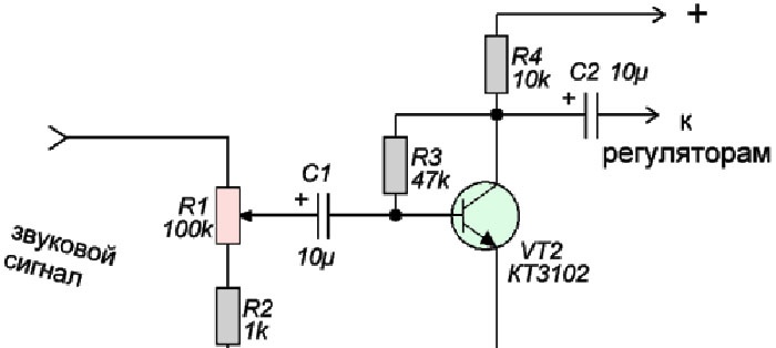
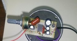
Any low-power transistor can be used; the domestic KT3102 has proven itself well in this circuit. Using tuning resistor R1, you can adjust the level of the signal supplied to the color music circuit. The amplifier is powered by the same 9 - 12 volts. You can even send a weak signal from your phone to its input, because it will be amplified to the desired level.
Assembling a simple color music
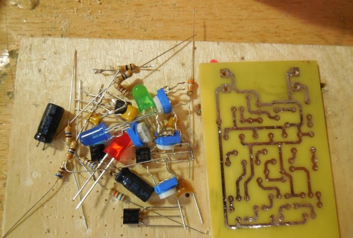
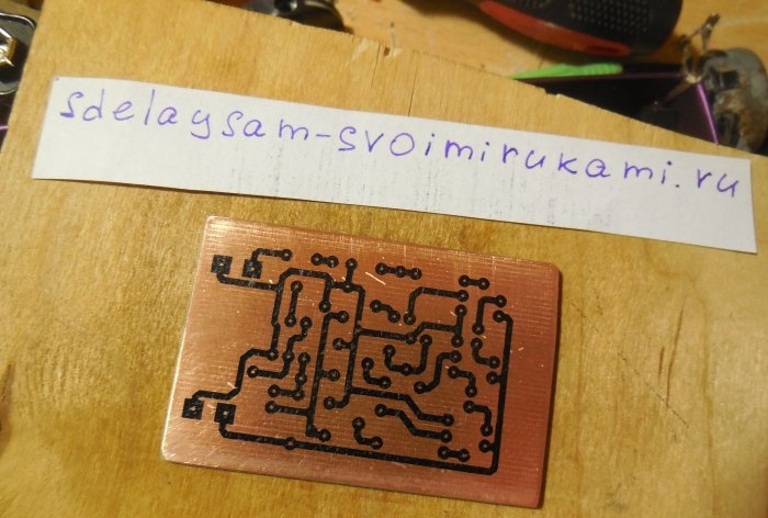
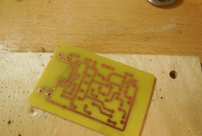
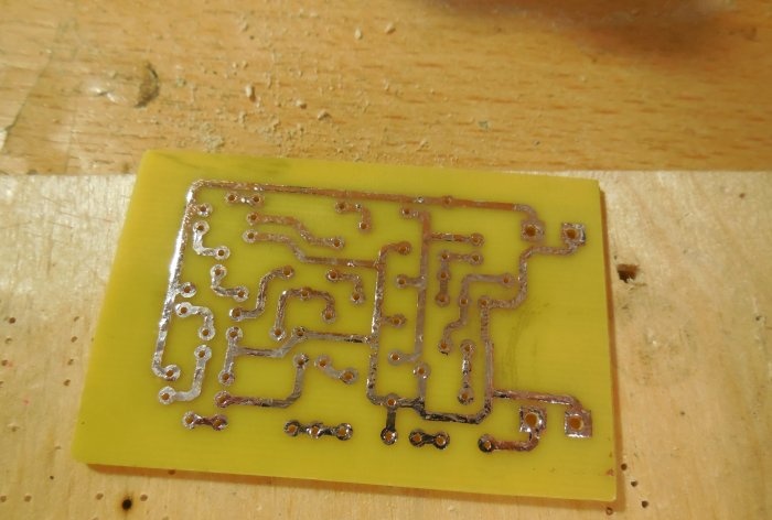
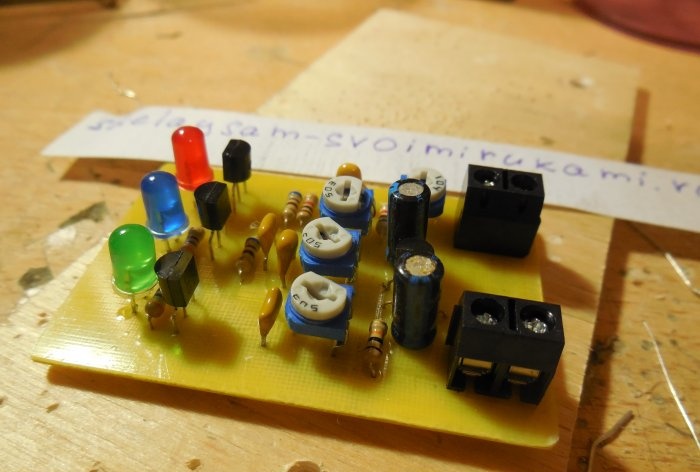
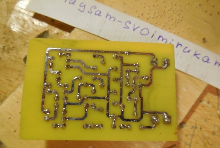
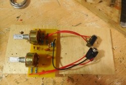
After analyzing the diagrams, you can proceed directly to assembling the structure. Both circuits can be assembled on one board, which is what I did. The printed circuit board has dimensions of 35x55 mm and is made using the LUT method. A few photos of the process: Download the board:After the excess copper has been removed, the holes have been drilled, and the tracks have been tinned, you can begin to solder the parts. Small parts - resistors - are soldered in first, followed by capacitors and transistors. Lastly, massive trimming resistors are installed on the board. To connect the power and sound signal wires, you can use terminal blocks, then connecting the wires will be much more convenient. After all the parts are sealed, it is necessary to wash the board from flux and test the adjacent tracks for short circuits.
First startup and setup
It is worth applying voltage to the board by connecting an ammeter to the gap in one of the power wires. When there is no signal at the input, the circuit consumes approximately 1-2 mA. All trimming resistors need to be turned to the middle position, after which a sound signal can be applied to the input of the circuit. To do this, you should use a splitter that plugs into the socket of your phone or player. In this case, the signal will simultaneously be sent to both the speakers and the color music board. Using R1, you need to ensure that the brightness of the LEDs is sufficient. Then, using resistors R4 - R6, each channel is adjusted separately so that the brightness of all LEDs is the same. After the circuit is configured, you can connect bright LED strips instead of individual LEDs, turn on the music louder and enjoy the work done. Happy building!
Watch the video
The work of such color music is clearly shown in the video:

