Automatic 12V charger
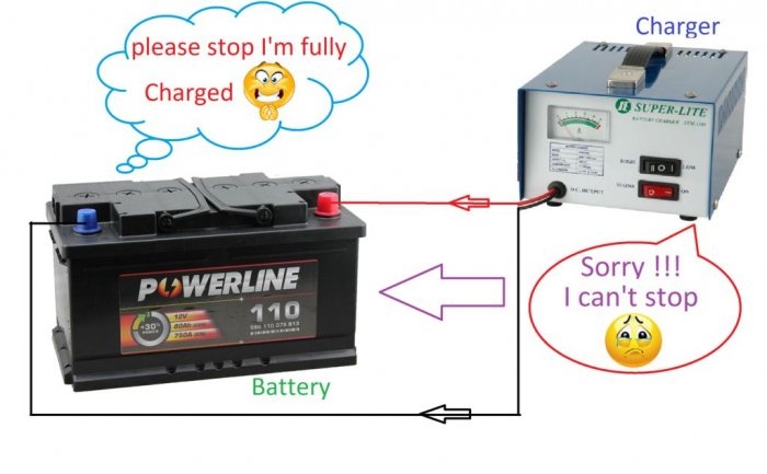
This is a very simple attachment circuit for your existing charger. Which will control the battery charge voltage and, when the set level is reached, disconnect it from the charger, thereby preventing the battery from overcharging.
This device has absolutely no scarce parts. The entire circuit is built on just one transistor. It has LED indicators that indicate the status: charging in progress or the battery is charged.
This device will definitely come in handy for motorists. For those who do not have an automatic charger. This device will turn your regular charger into a fully automatic charger. You no longer have to constantly monitor the charging of your battery. All you need to do is put the battery on charge, and it will turn off automatically only after it is fully charged.
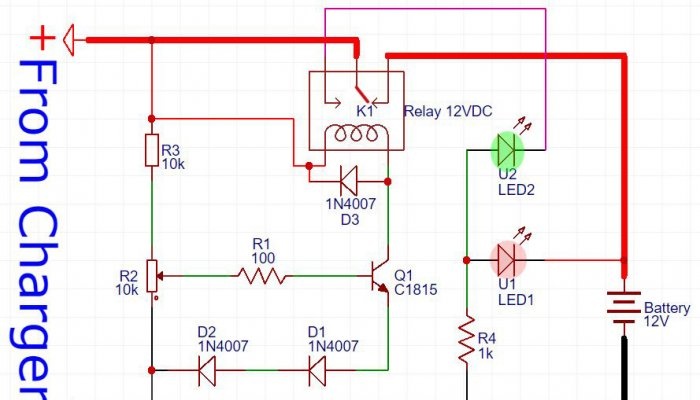
Here is the actual circuit diagram of the machine. In fact, it is a threshold relay that is activated when a certain voltage is exceeded.The response threshold is set by variable resistor R2. For a fully charged car battery, it is usually equal to - 14.4 V.
You can download the diagram here - http://www.mediafire.com/file/0ldtxs4ma6mt2q2/12V-Auto-Cut-Off-Charger_circuit_By_hokar_Fariq.pdf Source: https://home.washerhouse.com/en/?do=lastcomments
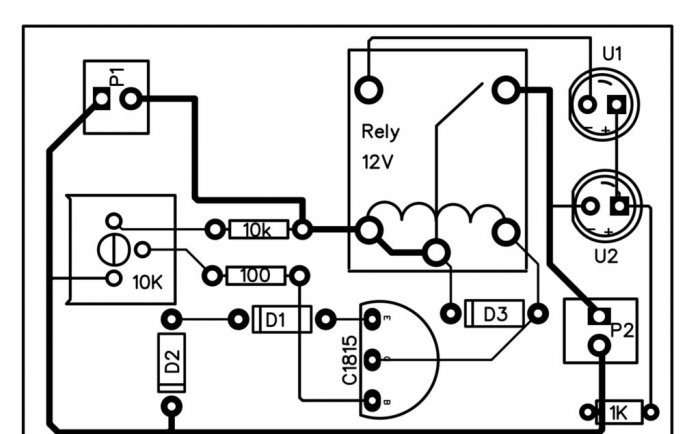
How to make a printed circuit board is up to you. It is not complicated and therefore can easily be laid out on a breadboard. Well, or you can get confused and make it on textolite with etching.
If all the parts are in good working order, setting up the machine is reduced only to setting the threshold voltage with resistor R2. To do this, we connect the circuit to the charger, but do not connect the battery yet. We move resistor R2 to the lowest position according to the diagram. We set the output voltage on the charger to 14.4 V. Then slowly rotate the variable resistor until the relay operates. Everything is set.
Let's play with the voltage to make sure that the console works reliably at 14.4 V. After this, your automatic charger is ready for use.
In this video you can watch in detail the process of all assembly, adjustment and testing in operation.
Original article in English
This device has absolutely no scarce parts. The entire circuit is built on just one transistor. It has LED indicators that indicate the status: charging in progress or the battery is charged.
Who will benefit from this device?
This device will definitely come in handy for motorists. For those who do not have an automatic charger. This device will turn your regular charger into a fully automatic charger. You no longer have to constantly monitor the charging of your battery. All you need to do is put the battery on charge, and it will turn off automatically only after it is fully charged.
Automatic charger circuit
Here is the actual circuit diagram of the machine. In fact, it is a threshold relay that is activated when a certain voltage is exceeded.The response threshold is set by variable resistor R2. For a fully charged car battery, it is usually equal to - 14.4 V.
You can download the diagram here - http://www.mediafire.com/file/0ldtxs4ma6mt2q2/12V-Auto-Cut-Off-Charger_circuit_By_hokar_Fariq.pdf Source: https://home.washerhouse.com/en/?do=lastcomments
Printed circuit board
How to make a printed circuit board is up to you. It is not complicated and therefore can easily be laid out on a breadboard. Well, or you can get confused and make it on textolite with etching.
Settings
If all the parts are in good working order, setting up the machine is reduced only to setting the threshold voltage with resistor R2. To do this, we connect the circuit to the charger, but do not connect the battery yet. We move resistor R2 to the lowest position according to the diagram. We set the output voltage on the charger to 14.4 V. Then slowly rotate the variable resistor until the relay operates. Everything is set.
Let's play with the voltage to make sure that the console works reliably at 14.4 V. After this, your automatic charger is ready for use.
Watch a video of the charger working
In this video you can watch in detail the process of all assembly, adjustment and testing in operation.
Original article in English
Similar master classes
Particularly interesting
Comments (13)

