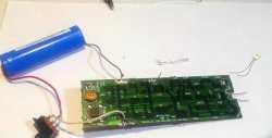
A simple LED flasher on an optocoupler
Optocoupler PC817 is a very common galvanic isolation element. It is available in almost every switching power supply, be it a phone charger or a computer unit. So it won't be difficult to get it. Based on this transistor optocoupler, you can assemble a very simple LED flasher with a stroboscopic effect.

First, let's take a look at the optocoupler itself. It consists of two elements united by optical communication. That is, if you apply voltage to Light-emitting diode, the transistor inside will open.

Note that the dot represents the first contact for reference. The element itself has 4 contacts. 1, 2 - this is the input for connecting internal LED. 3, 4 - output from the transistor.
On the basis of this simple radio element, a simple multivibrator is built - a generator of repeating pulses.
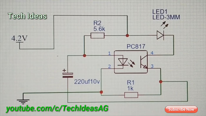
The circuit does not require adjustment and, with fully functional elements, starts working immediately.
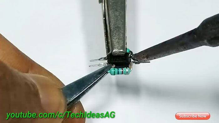
Assembly is carried out by hanging installation without a board.We clamp the optocoupler in the clamp and solder two resistors according to the diagram.
Next we solder Light-emitting diode. Pay attention to the polarity of its inclusion.
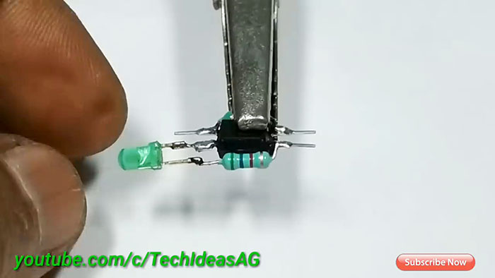
Next we solder the capacitor.
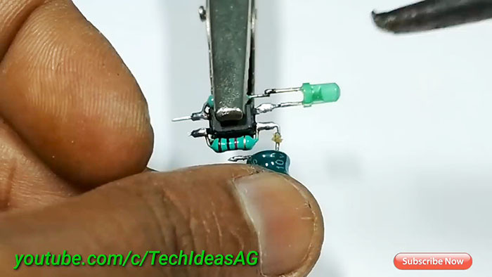
The connecting tracks are made from tinned wire.
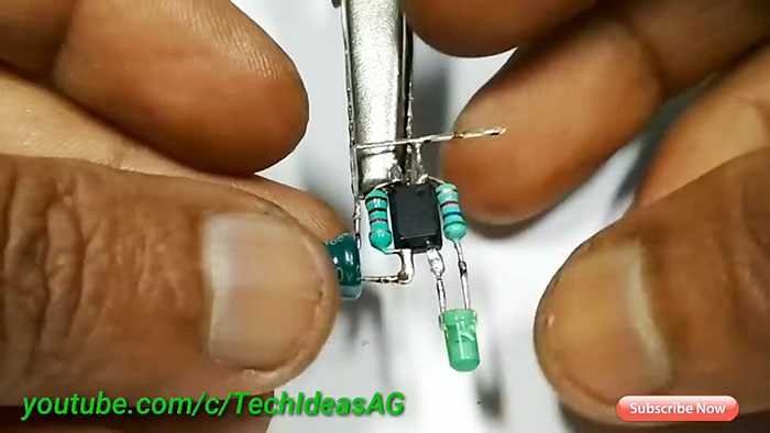
We bring the scheme to the end.
Solder the battery contacts.
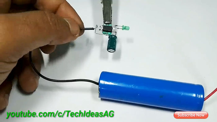
The flasher starts flashing. It's simple.

The blinking frequency can be adjusted by the capacitor capacitance.
If suddenly something does not start, check the polarity of all elements except resistors.
I think you can easily find a use for this simple scheme.
You can evaluate the operation of the flasher in the video.

Will need
- 3.7V lithium battery (fully charged 4.2V).
- Light-emitting diode any color.
- Two resistors of 1 kOhm and 5.6 kOhm.
- Transistor optocoupler PC817.
- Capacitor 220 uF 10 V.
Making a flasher using an optocoupler
First, let's take a look at the optocoupler itself. It consists of two elements united by optical communication. That is, if you apply voltage to Light-emitting diode, the transistor inside will open.

Note that the dot represents the first contact for reference. The element itself has 4 contacts. 1, 2 - this is the input for connecting internal LED. 3, 4 - output from the transistor.
Simple flasher circuit
On the basis of this simple radio element, a simple multivibrator is built - a generator of repeating pulses.

The circuit does not require adjustment and, with fully functional elements, starts working immediately.
Assembly is carried out by hanging installation without a board.We clamp the optocoupler in the clamp and solder two resistors according to the diagram.

Next we solder Light-emitting diode. Pay attention to the polarity of its inclusion.

Next we solder the capacitor.

The connecting tracks are made from tinned wire.

We bring the scheme to the end.
Examination
Solder the battery contacts.

The flasher starts flashing. It's simple.

The blinking frequency can be adjusted by the capacitor capacitance.
If suddenly something does not start, check the polarity of all elements except resistors.
I think you can easily find a use for this simple scheme.
Watch the video
You can evaluate the operation of the flasher in the video.
Similar master classes
Particularly interesting
Comments (6)

