How to make a proximity-obstacle sensor
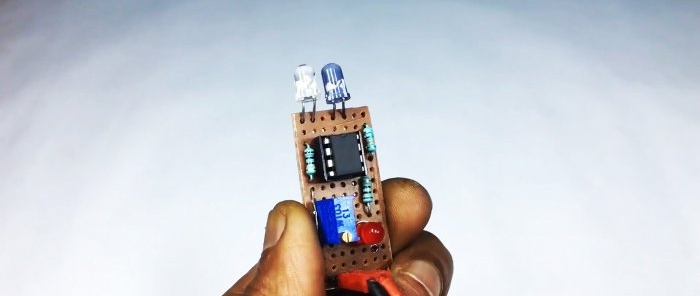
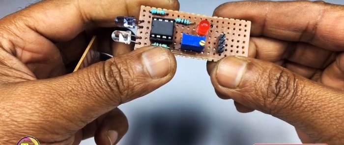
This obstacle (proximity) sensor consists entirely of accessible parts, with a minimum number of them. It has high, adjustable sensitivity and is able to detect an object at a distance of up to 0.5 meters. It can be useful for various purposes in radio electronics and robotics. Perfect for assembly by beginning radio amateurs.
Will need
- Chip LM358 -
- IR diode -
- Photodiode -
- Light-emitting diode -
- Resistors 100 Ohm, 10 kOhm -
- Variable kOhm resistor.
- Universal board -
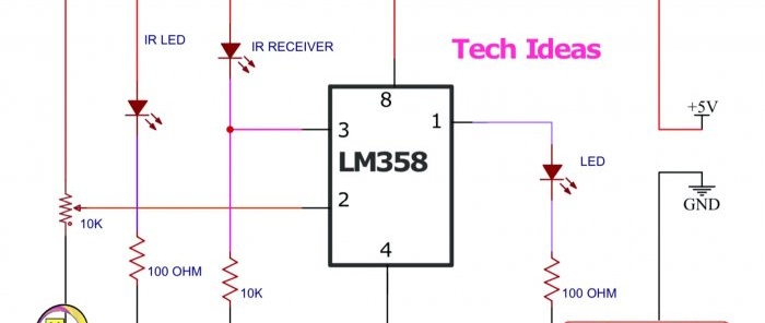
Obstacle sensor circuit
The LM358 operational amplifier contains a comparator that monitors the state between the levels of two circuits. A variable resistor regulates the response level.
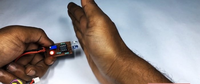
The principle of operation is very simple: the IR diode lights up constantly. As soon as an object appears in its path, the beam will be reflected from it and hit the photodiode. The level in the photodiode circuit will change and the comparator will operate, causing the Light-emitting diode.
See a simpler diagram here - https://home.washerhouse.com/en/3877-prostoy-infrakrasnyy-sensor.html
Assembling a proximity-obstacle sensor
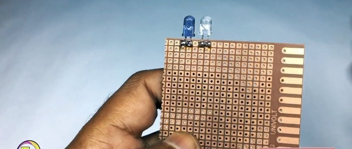
For assembly we will use a universal board.Solder the photodiode and IR diode. They should look in the same direction.
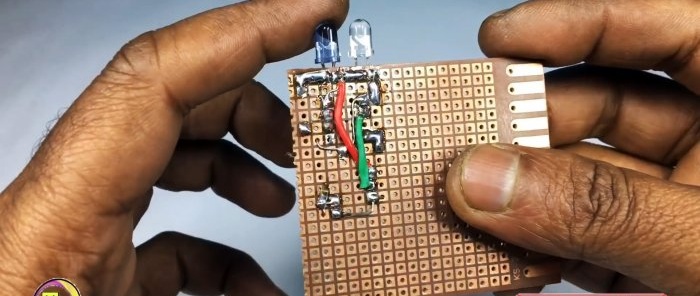
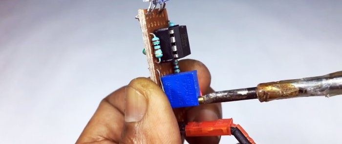
Next, install all the components according to the diagram and solder them. We use wire scraps as board conductors.
We cut off unnecessary parts of the textolite board.
We supply power and rotate the variable resistor motor to achieve the desired sensitivity.
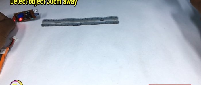
We check the work on an obstacle at a distance of 30 centimeters.
When any object enters this zone, Light-emitting diode starts to glow.
This sensor is insensitive to daylight, but still responds to it, so in the future it is possible to assemble a tube-shaped screen for the photosensor.
Watch the video
Similar master classes
Particularly interesting
Comments (0)

