How to make a universal 0-25 V power supply from a computer unit
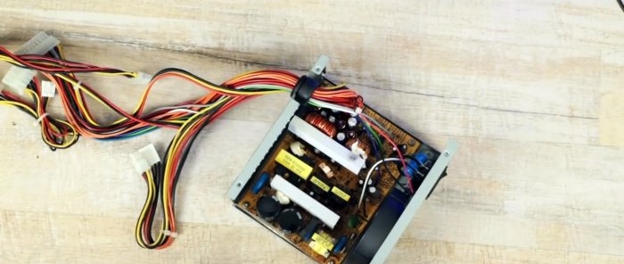
If you have a power supply from an old computer lying around, you can easily use it and turn it into an adjustable, laboratory power source.
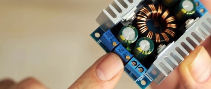
This instruction is good because it does not require knowledge of the circuitry of pulsed sources. The block circuit will remain untouched, and adjustment will be made using a universal converter.
Will need
- Universal converter 1.25-30 V 8 A - http://alii.pub/5qwyq4
- Monitor 4 in 1: voltmeter, ammeter, wattmeter, energy meter - http://alii.pub/5qwyqw
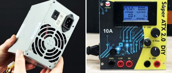
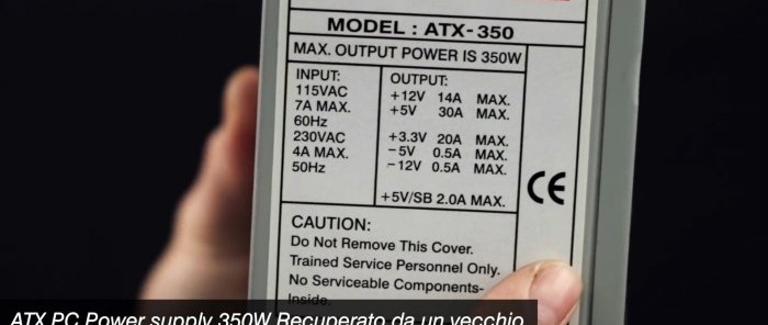
- Old computer unit.
350 W unit.
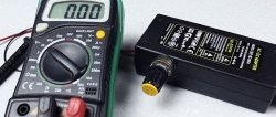
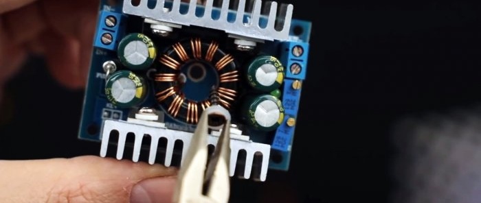
A universal converter that can not only increase but also decrease voltage. All output values are stabilized.
Peak current 10 A, short-term current 8 A, continuous current - 6 A. Output voltage 1.25-30 V.
Converting an ATX block into a universal, regulated power supply
Unscrew the screws and open the block cover.
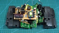
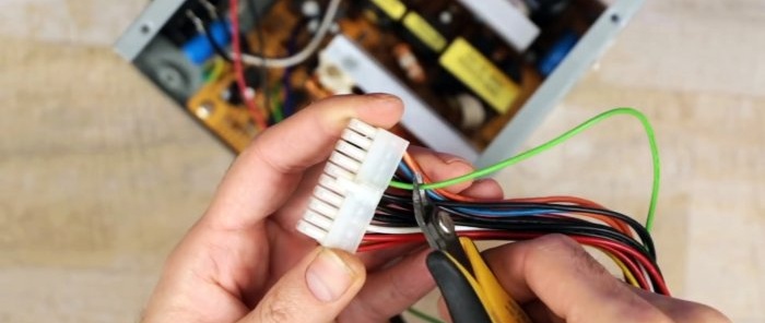
We cut off the connection block.
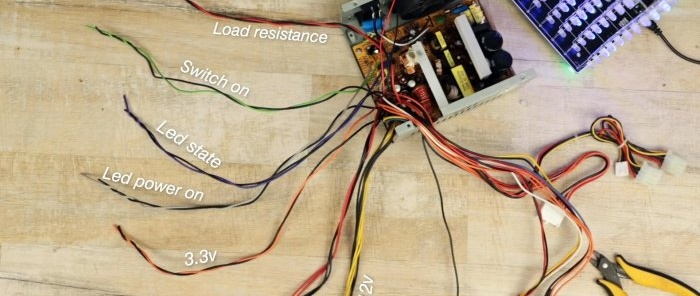
We separate the wires into groups.
If you don’t know the diagram of all the outputs, then search the Internet by the brand of the source.
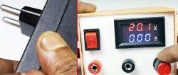
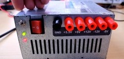
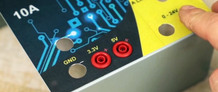
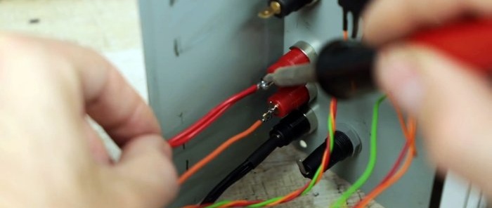
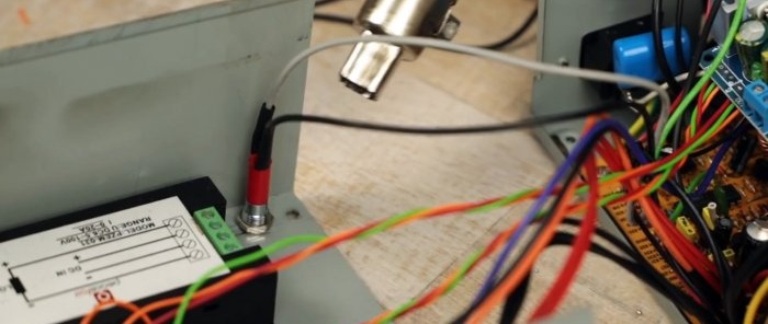
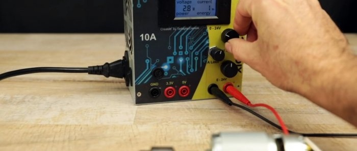
The front panel will display: power button, Light-emitting diode availability of food. Also terminals “-”, “+3.3 V”, “+5 V”. 12 volt voltage will be supplied to the converter, from the converter to the monitor, and from the monitor to the “0-25 V” output terminal.
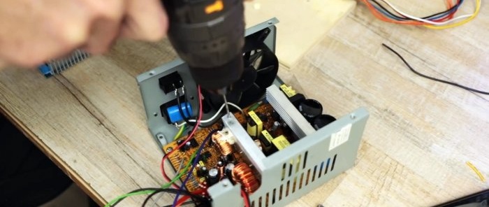
Drill a hole in one of the radiators to mount the converter.
Drill a hole in the center of the converter.
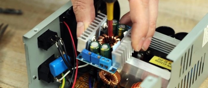
We screw it onto the radiator using a self-tapping screw through a dielectric gasket.
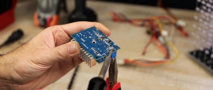
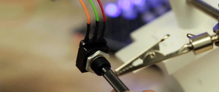
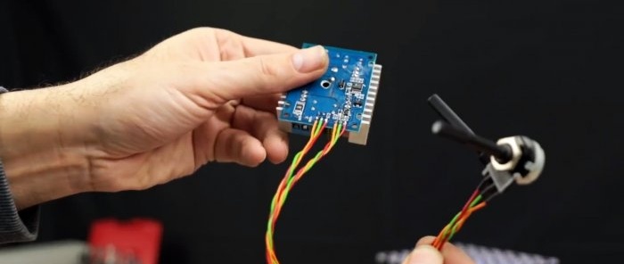
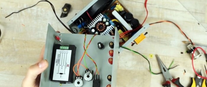
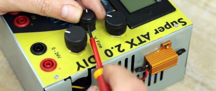
The mount is ready. Next, unscrew and unsolder the variable resistors. One regulates the output voltage, the other limits the current.
Instead, we solder remote variable resistors.
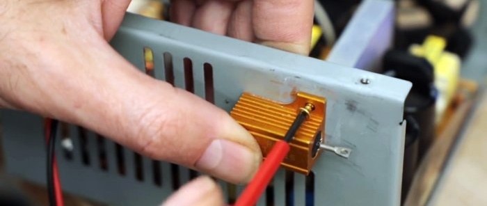
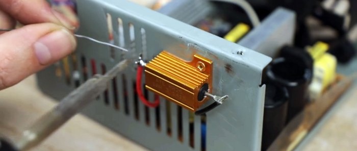
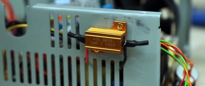
This pulse source will not work without a load on the 5 V bus. Therefore, let's take a powerful 10 Ohm 10 W resistor and attach it to the case.
We solder the wires and insulate them with heat shrink.
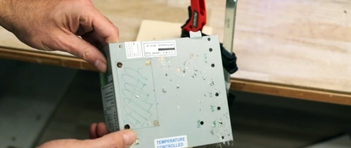
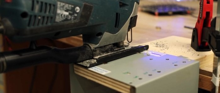
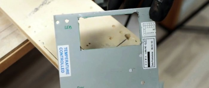
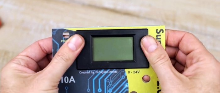
Next, in the block cover we will make all the necessary holes for LEDs, power button, output terminals, window under the monitor.
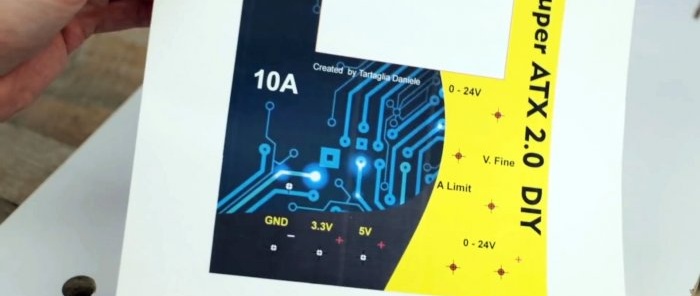
For an aesthetic appearance, you can print the panel nameplate.
We glue it and install all the elements on the front part.
We solder everything true.
Close the case and secure it with screws. Install the potentiometer knobs.
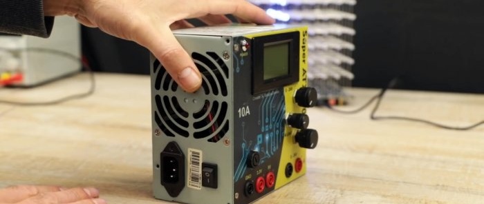
The laboratory source is ready for use.
Watch the video
Similar master classes
