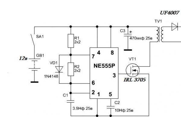
Converter circuit for gauss gun
The converter is based on the popular 555 series timer. The design of the converter is quite simple and cannot cause any difficulties even for novice radio amateurs.
The power of such a converter largely depends on the field-effect transistor used. The main types of field effect transistors used are IRFZ44, IRL3705, IRF3205. The last two work great, but on the first one you can observe a large heat release, although the transistor needs a heat sink.
The power of the converter directly depends on the power source; with an uninterruptible power supply battery the power is about 50-60 watts or more.
Such a converter will be able to charge a 400 volt 1000 µF capacity in just one second! and all this thanks to the increased power of the converter.
As you know, the 555 series microcircuit can operate in two modes - 1) as a timer (the main purpose of the microcircuit), 2) as a rectangular pulse generator, in our case, the microcircuit works as a master oscillator.
The pulses generated by the microcircuit go to the gate of a powerful field-effect transistor, as a result, it forces it to open and close at a given frequency (the frequency of the generated pulses), forming a high-frequency alternating voltage in the primary winding of the transformer.
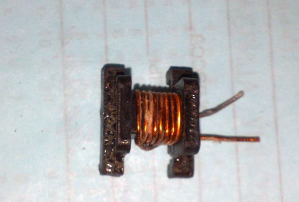
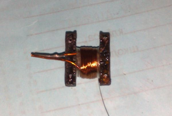
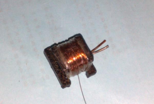
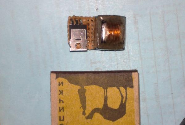
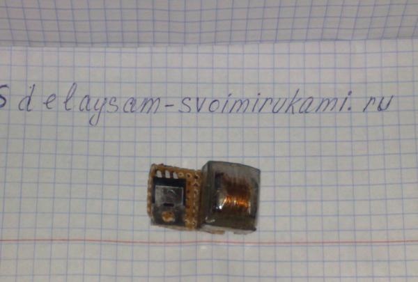
The primary winding of the transformer consists of 7 turns of 1 mm wire; you can also use several strands of thinner wire for convenient winding.
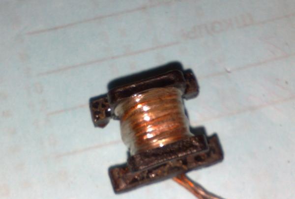
Next, we put insulation on top of the primary winding and wind the secondary. The winding consists of 120 turns of wire with a diameter of 0.2-0.3 mm.
The winding is wound in layers, each layer has 40 turns. Scotch tape, insulating tape, fluoroplastic, etc. can be used as interlayer insulation.
The power of the converter is quite high, so the circuit can be used as a 12-220 volt converter, but in this case the number of turns in the secondary winding must be reduced to 65.
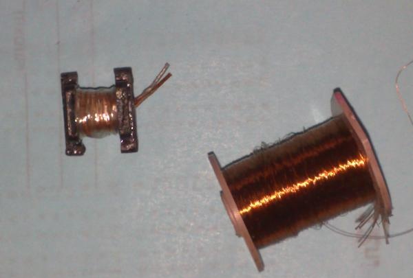
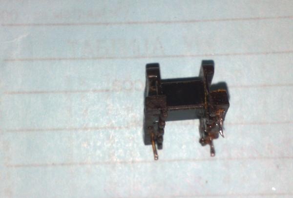
The transformer can be wound on a ferrite ring, armor cup or W-shaped frame (ferrite), the dimensions are not very important, the main thing is that the windings fit.
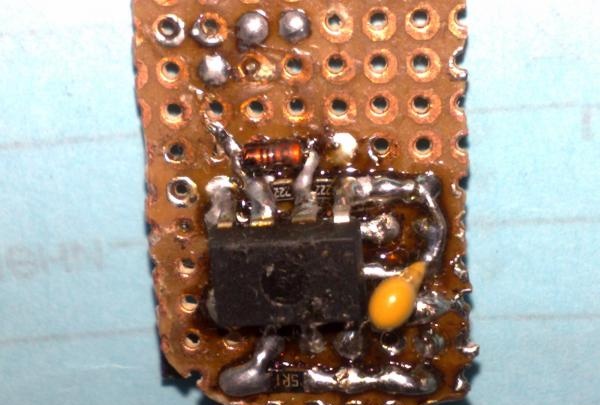
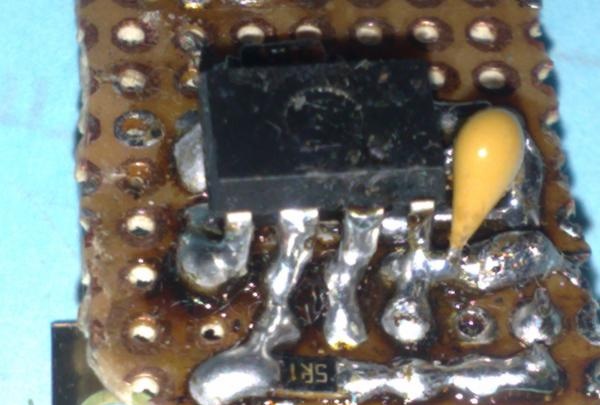
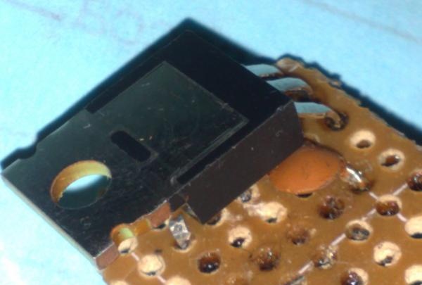
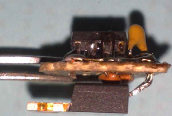
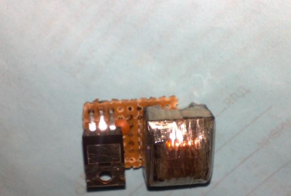
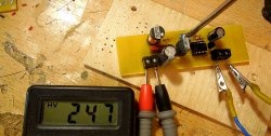
In my case, the installation is done on a breadboard on both sides. SMD components were also used to reduce the size of the board. The transformer was also mounted on the board.
The output voltage of the converter is about 380-440 volts; for rectification, you can use any pulse diodes with a voltage of 1000 volts and a current of at least 1 Ampere (FR107, FR207, UF4007 and others).
The power of such a converter largely depends on the field-effect transistor used. The main types of field effect transistors used are IRFZ44, IRL3705, IRF3205. The last two work great, but on the first one you can observe a large heat release, although the transistor needs a heat sink.
The power of the converter directly depends on the power source; with an uninterruptible power supply battery the power is about 50-60 watts or more.
Such a converter will be able to charge a 400 volt 1000 µF capacity in just one second! and all this thanks to the increased power of the converter.
As you know, the 555 series microcircuit can operate in two modes - 1) as a timer (the main purpose of the microcircuit), 2) as a rectangular pulse generator, in our case, the microcircuit works as a master oscillator.
The pulses generated by the microcircuit go to the gate of a powerful field-effect transistor, as a result, it forces it to open and close at a given frequency (the frequency of the generated pulses), forming a high-frequency alternating voltage in the primary winding of the transformer.
The primary winding of the transformer consists of 7 turns of 1 mm wire; you can also use several strands of thinner wire for convenient winding.
Next, we put insulation on top of the primary winding and wind the secondary. The winding consists of 120 turns of wire with a diameter of 0.2-0.3 mm.
The winding is wound in layers, each layer has 40 turns. Scotch tape, insulating tape, fluoroplastic, etc. can be used as interlayer insulation.
The power of the converter is quite high, so the circuit can be used as a 12-220 volt converter, but in this case the number of turns in the secondary winding must be reduced to 65.
The transformer can be wound on a ferrite ring, armor cup or W-shaped frame (ferrite), the dimensions are not very important, the main thing is that the windings fit.
In my case, the installation is done on a breadboard on both sides. SMD components were also used to reduce the size of the board. The transformer was also mounted on the board.
The output voltage of the converter is about 380-440 volts; for rectification, you can use any pulse diodes with a voltage of 1000 volts and a current of at least 1 Ampere (FR107, FR207, UF4007 and others).
Similar master classes


Particularly interesting


Comments (22)
