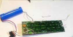
Easy conversion of ATX into a charger with your own hands
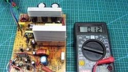
In the first article (https://home.washerhouse.com/en/7634-prostaja-peredelka-ath-v-zarjadnoe-ustrojstvo.html) I told you how to remake an ATX power supply. Implemented current and voltage regulation.
Now you need to make adjustments to suit your needs.
I will set the voltage range from 5-6 to 15 volts. The current remains unchanged. Why is this so? The charger will be used to charge 6 and 12 volt batteries. There is one more catch, but more on that later.
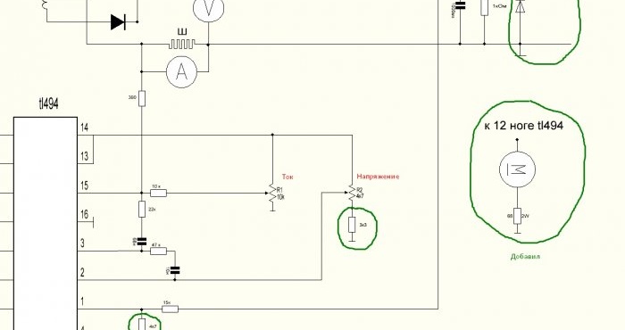
Briefly about the scheme
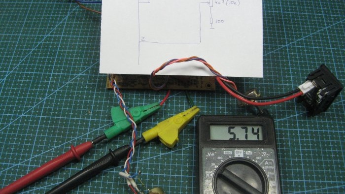
The components that I added are highlighted in green. In series with the “Voltage” regulator, I added a 3.3 kOhm resistor. So I limited the minimum voltage. In series with the 2.7 kOhm resistor, from the first leg, I installed a 4.7 kOhm resistor. This is how it turned out to limit the maximum voltage. At the output of the power supply I installed a chain of a diode and a fuse. The result was the simplest protection against polarity reversal. If the battery is connected incorrectly, current flows through the diode and the fuse blows. The fan is connected to the power supply of the PWM chip. I installed a 68 Ohm resistor with a power of 2 Watts to limit excess voltage. The power supply for the microcircuit is about 22 Volts.
Main details
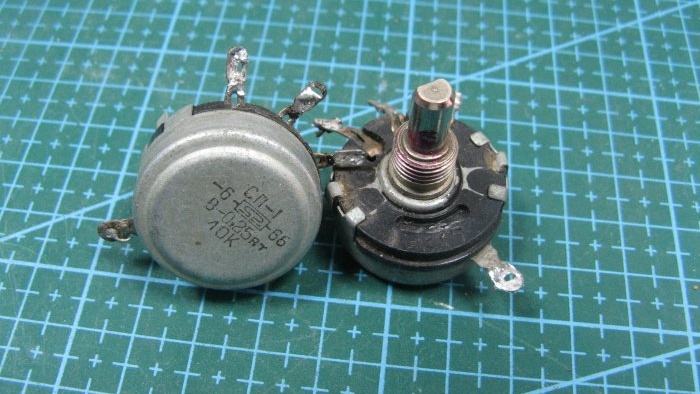
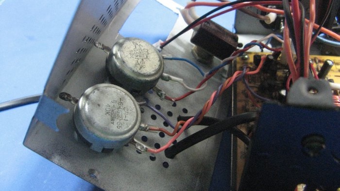
I'll use Soviet resistors, I found a couple of handles from them.
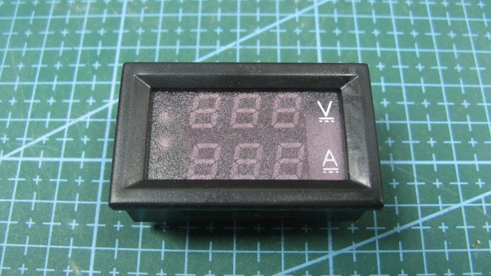
My indicator is a Chinese volt-ampere meter - http://alii.pub/5s8fk9
So about the output voltage. I bought the wrong indicator, but it is powered by the measured voltage. Its power supply is from 4.5 Volts. Therefore, the voltage was torn from 5-6 Volts.
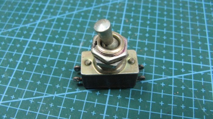
Power switch from an old TV.
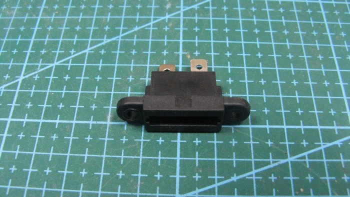
I will install the fuse through the mount. It's a standard car one, I'll set it to 10 amps.
I had the board without a case, I found a suitable one.
Converting a computer block into a charger with your own hands
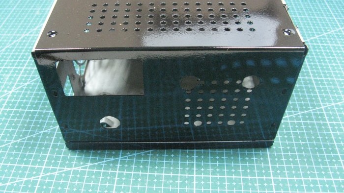
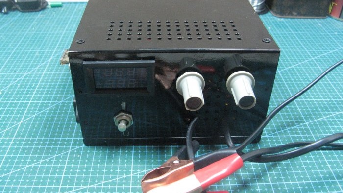
Marked and cut out all the holes. I spray painted it. I painted with what I had, barely enough for the body. All prints are not visible on it.
Installed the board into the case. I screwed in the resistors and the switch.
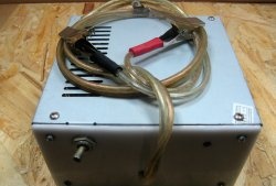
Installed wires with crocodiles. Wires are double insulated, two wires in parallel. Each wire is 0.5 VK. mm. It turned out well.
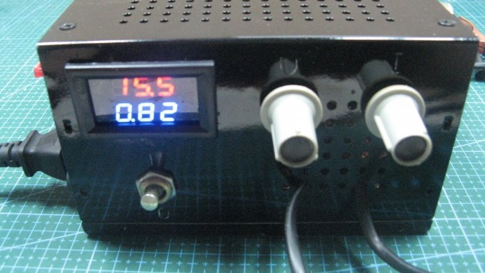
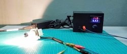
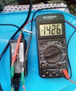
Oh yes. Minimum voltage in the photo.
Maximum 15.5 Volts. I replaced the voltage adjustment resistor, so the output voltage is slightly different from the original one.
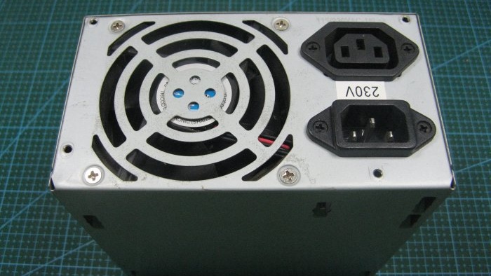
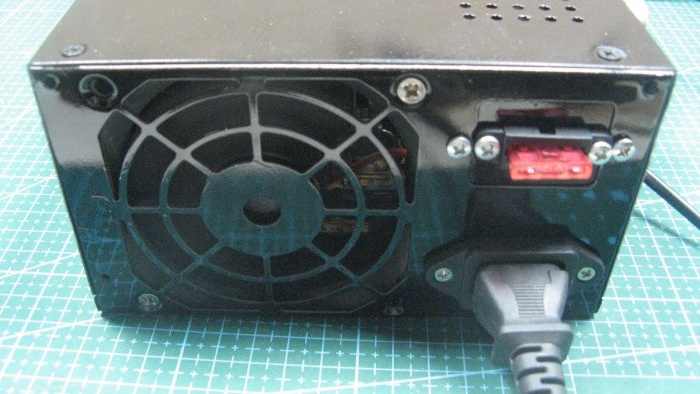
This is how the unit looks from the side of the power cable and fuse.
Customize power supplies to suit your needs. The blocks are now available inexpensively. The schemes are approximately similar. All that remains is to remove the excess and add what is missing. The conversion scheme is relevant for most ATX units.

