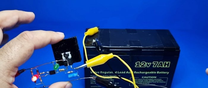
12 V battery automatic shutdown circuit without microcircuits and relays
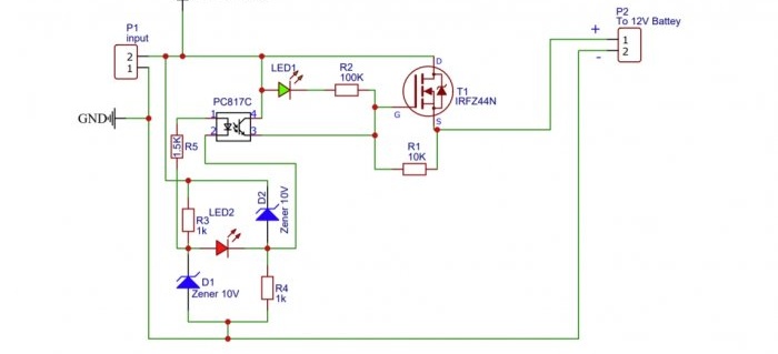
Please note that this circuit is made without a relay and a microcircuit. Its automatic shutdown occurs due to the reference voltage created by the zener diode. But the device is designed more for charging new batteries, since it is interrupted at the “gassing voltage” of 14.2-14.8 V. Many old (sulfated) batteries cannot reach this voltage and risk overcharging.
The choice of power source for the circuit depends on the battery capacity; the optimal ratio is 10/1, but 18 V or higher is required. This is justified by the fact that if there is a loss of power caused by the field-effect transistor, the battery will not be fully charged.
Details
- Transistor IRFZ44N - http://alii.pub/5ct567
- Zener diode 10 V - 2 pcs. - http://alii.pub/5myg53
- Optocoupler PC817 - http://alii.pub/65k075
- Resistors: 100 kOhm; 10 kOhm; 1.5 kOhm; 1 kOhm - 2 pcs. - http://alii.pub/5h6ouv
- Two LED different color - http://alii.pub/5lag4f
Making a circuit to automatically disconnect the battery from the charger
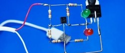
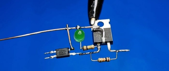
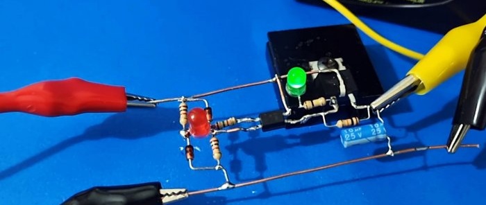
To build the circuit, the drain leg of the “field worker” is bent and a busbar is soldered to it, which will then be used as a base. A green one is installed between the drain and the gate through a 100 kOhm resistance. Light-emitting diode (plus on stock). Also, a resistance of 10 kOhm is used to bridge the gate-source of the transistor. A single-channel optocoupler (optocoupler) PC817 is soldered to the resulting circuit. Its collector is hung on the drain, and the emitter on the gate of the transistor.
Next, take two 10 V zener diodes and two 1 kOhm resistors. You cannot install zener diodes at 12 V, as the voltage drop will be different and the battery may be damaged.
The anodes and cathodes of Zenner diodes are connected with opposite polarity through resistors. Red is soldered between them Light-emitting diode (plus on the cathode).
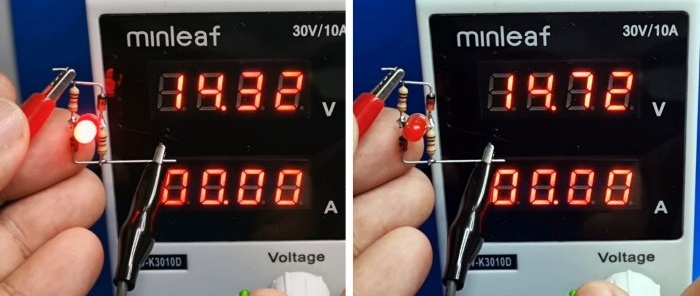
When a voltage of 8 V or more is applied to the assembled bridge, red Light-emitting diode lights up, when the 14.8 V mark is reached, the circuit gives a cutoff and Light-emitting diode goes out.
We solder it to the previously assembled assembly. To do this, the plus of the LED is connected through a 1.5 kOhm resistor to the anode of the optocoupler, and its minus directly to its cathode.
The free cathode of the zener diode is connected to the drain of the transistor, and the free anode of the second zener diode is soldered through a 10 uF 25 V electrolyte to the source of the field switch (“-” capacitance at the source).
We get the input of the circuit between the free cathode and the free anode of the zener diodes, as well as its output between the field source and the minus of the capacitance.
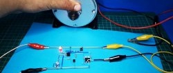
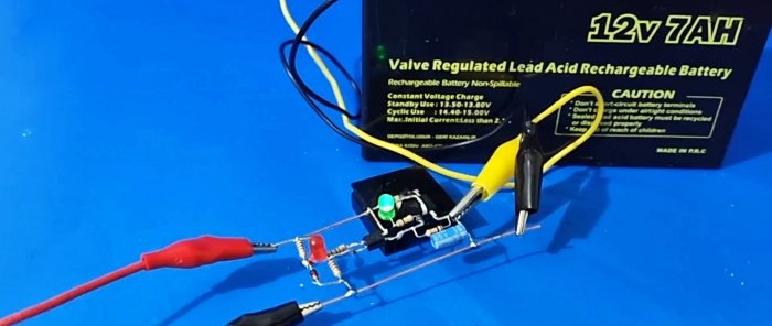
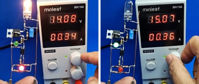
By connecting the circuit and giving it a load, you can see that when a voltage of 8 V is applied, the red LED lights up. This happens until the level of 14.8 V is reached. Then the red LED goes out and the green LED lights up.
In practice, this means that the device breaks the circuit when the battery has reached its maximum charge.This is also indicated by the green LED lighting up. A 60 A/h battery at a current of 6 A takes approximately 10 hours to charge. In this case, the MOSFET can become very hot. To prevent it from burning, it is better to place it on the radiator.
Watch the video
Similar master classes
