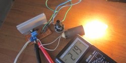
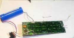
An interesting diagram of a simple soft starter using a relay without transistors or microcircuits
An interesting device is made in the form of a simple discrete regulator and is designed for a two-stage increase in electrical power supplied to a light bulb or other load from a direct current source. At the moment the supply voltage is applied, the regulator forcibly limits the current flowing through the load. Then, after some time, it abruptly increases it to the maximum.
It is distinguished by: simplicity of the circuit, since it contains neither microcircuits nor transistors; the use of inexpensive and easily accessible components; allows both the load power and the delay time interval to vary at the intermediate level.
Schematic diagram
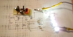
The electrical circuit of the regulator is shown in the sketch.
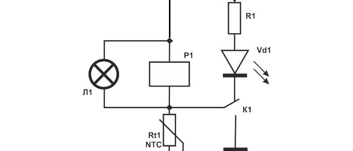
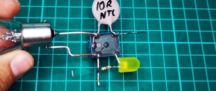
An electromechanical relay “P1” with a working contact for switching was used as a regulator. The deceleration time for supplying maximum power to the load is set by the thermistor “Rt1” with a negative temperature coefficient. Current limiting resistor “R1” determines the maximum load power.
A 12-volt battery or laboratory source is used to create the supply voltage. By changing the supply voltage you can also change the maximum power of the connected load.
Element base
The discrete controller is assembled from the following components:- Relay 10A - http://alii.pub/5y3wwl
- Thermistor 10 Ohm - http://alii.pub/5y3wvm
- Resistor 150 – 250 Ohm - http://alii.pub/5h6ouv
- Light-emitting diode - http://alii.pub/5lag4f
When assembling the circuit, it may be necessary to select the resistances of both the constant resistor R1 and the thermistor Rt1. If the load switches too quickly to maximum power mode, the value of the thermistor should be increased; if switching is slow, the value of the current-limiting resistor R1 should be reduced.
Circuit installation
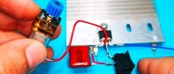
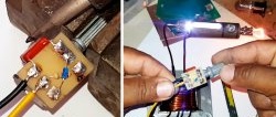
The regulator can be mounted on a printed circuit board or other circuit board, as well as suspended. In the latter case, it is best to use relay P as the supporting base, since it is the most mechanically stable component of the circuit. During assembly, the remaining elements are connected by soldering to standard terminals or by sections of insulated mounting wires.
Regulator operation
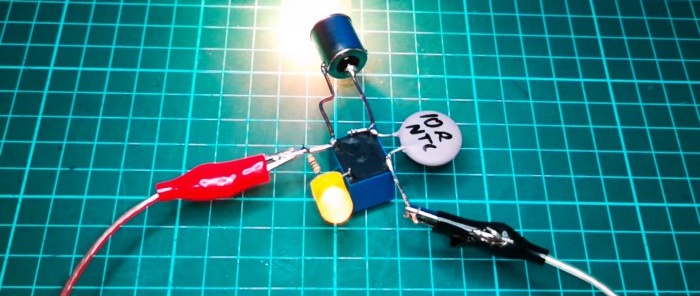
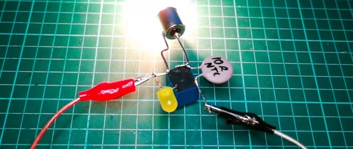
The regulator works as follows. At the moment the supply voltage is applied, the current through the load is set by the voltage drop across the winding of relay P1, determined, in turn, by the source voltage and the resistances of the resistor R1 and thermistor Rt1 connected in series. The load receives intermediate power, which is indicated by the lit LED Vd1.
When Rt1 heats up, the resistance of the R1-Rt1 chain drops, the current through the winding of relay P increases, contact K1 is activated, which short-circuits the thermistor Rt1 and reliably switches relay P1 to the on state.Additionally, the circuit of current flow through Light-emitting diode Vd1, which goes out.
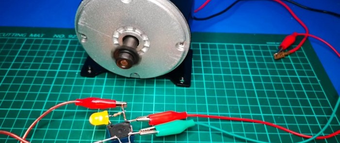
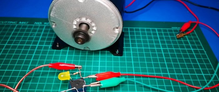
Operation of the circuit with a DC motor.
Full power is supplied after an interval of 3-5 seconds.

