Ultra-simple level indicator without transistors and microcircuits
There are circuits of simple signal level indicators that do not contain transistors or microcircuits. They don't even require a power source to operate. And the time spent on assembly will not exceed 20 - 30 minutes. Although, to be honest, the end result will be a simple light and music design, for example, speakers. There is no need to talk about the accuracy of such indicators. Let's put together one of the most common schemes that roam the Internet.
Making a level indicator without transistors and microcircuits
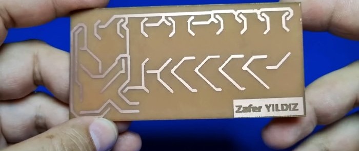
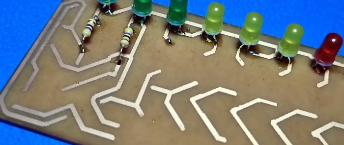
Considering the simplicity of the circuit and the minimum of parts used for the indicator, the device can even be assembled using wall-mounted installation. But if you are not lazy and make at least the simplest printed circuit board, then your homemade product will look more complete, more stylish. Let's start assembling.
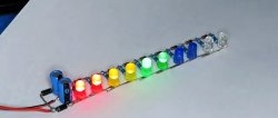
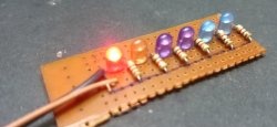
For greater visual effect, it is better to take multi-colored ones. LEDs. Typically, indicators use three colors: green, yellow and red. Let's not “reinvent the wheel”; the indicator will comply with the canons.
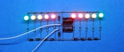
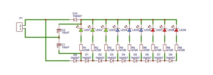
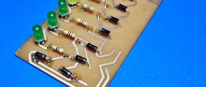
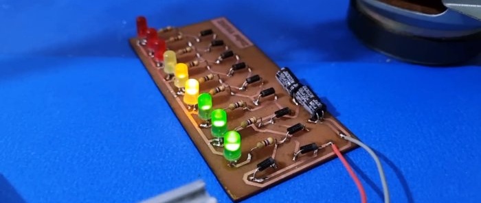
To limit current LEDs will be required resistors. Their denomination 470 Ohm. The parts are installed on the board and soldered. Now it's your turn diodes. Used 1N4007.
A kind of “ladder” is assembled from them, at each “step” of which the voltage drop will be about 0.3 Volts. And the corresponding one will light up Light-emitting diode.
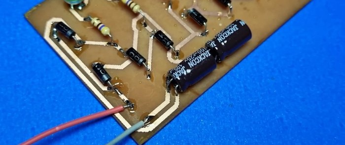
In addition to the indicator part itself, you will need an input voltage doubler. It is assembled from two diodes and two electrolytic capacitors. Well, that's all. Now check.
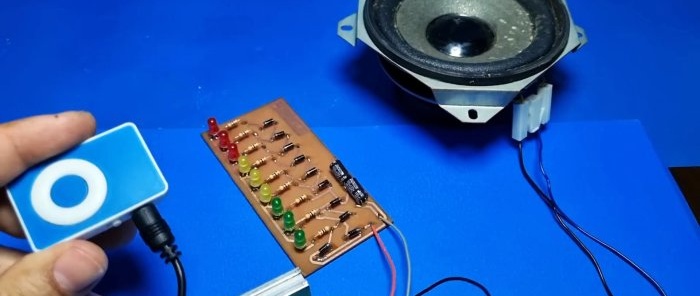
The signal supplied directly from the output of the MP3 player is not sufficient for the indicator to work.
Required ULF.
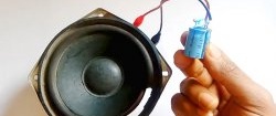
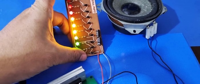
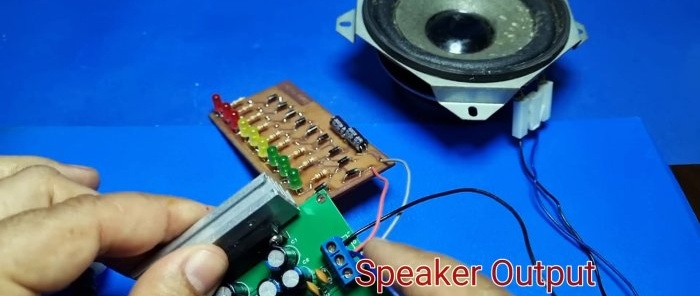
It is convenient to remove the signal from the speaker terminals. Multi-colored lights flash to the music. The device is working.
Watch the video
Similar master classes
