Control Panel for PC
We will need:
switch (they should have 3 legs, and the switch should have 3 positions).
switch (key type, optional).
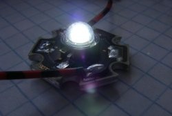
4 blue LED and 5 red ones.
4 red LED .
11 resistors 750 Ohm.
Wires.
Heat shrink tubing or super glue.
Soldering iron and accessories.
Face plug.
3 power supply splitters.
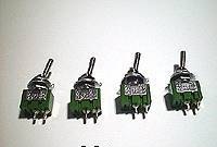
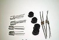
Characteristics LEDs:
Voltage = 1.5 V, Current = 0.015 A.
From here we calculate the required resistance for incoming 12 V:
R = (12 V - 1.5 V) / 0.015 A = 700 Ohm
or the closest value that can be achieved, 750 ohms
Let's start, let's take the front plug....
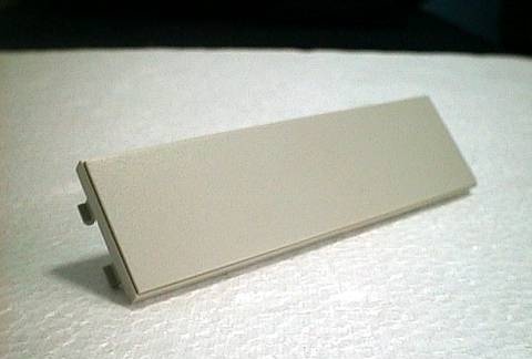
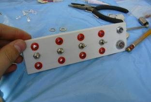
.... and drill holes in it for switches and LEDs.
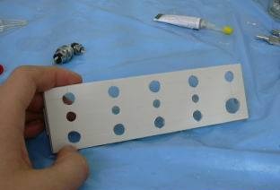
And we screw all this stuff into a plug.
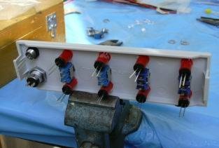
Now we turn all this stuff over to the other side, it’s better to tighten the plug in a vice, otherwise it will crawl across the table during soldering.
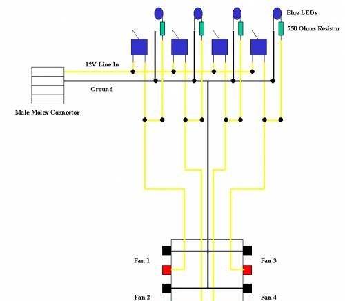
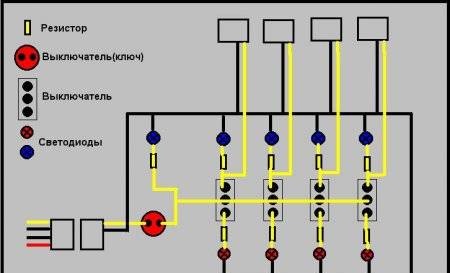
We solder everything approximately according to this scheme, or as you need.
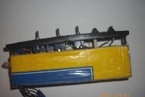
Eventually:
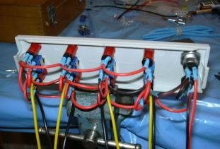
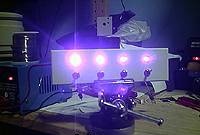
We check the operation - when the switch is removed from the neutral position, one LED should light up.
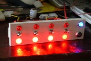
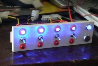
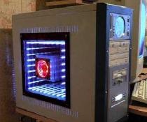
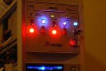
We build it into the body.And we manage what we want :-))
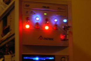
Second option: You can get by with one row of LEDs and switches without a neutral position:
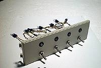
Here's the diagram:
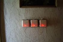
Job:
All !
Similar master classes
Particularly interesting
Comments (7)

