Current presence indicator
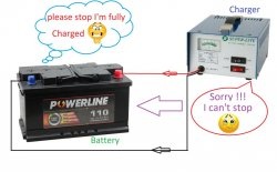
There may be a need to monitor the presence of current flowing in a circuit in two states: either present or not. Example: you are charging a battery with a built-in charging controller, connected to a power source, but how to control the process? You can, of course, include an ammeter in the circuit, you say, and you will be right. But you won't do this all the time. It’s easier to once build a charge flow indicator into the power supply, which will show whether current is flowing into the battery or not.
Another example. Let’s say there is some kind of incandescent lamp in a car that you don’t see and don’t know whether it’s on or has burned out. You can also include a current indicator in the circuit to this lamp and monitor the flow. If the lamp burns out, it will be immediately visible.
Or there is some kind of sensor with a filament. Tapa gas or oxygen sensor. And you need to know for sure that the filament has not broken and everything is working properly. This is where the indicator comes to the rescue, the diagram of which I will give below.
There can be a lot of applications, of course the main idea is the same - monitoring the presence of current.
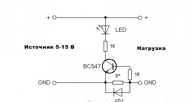
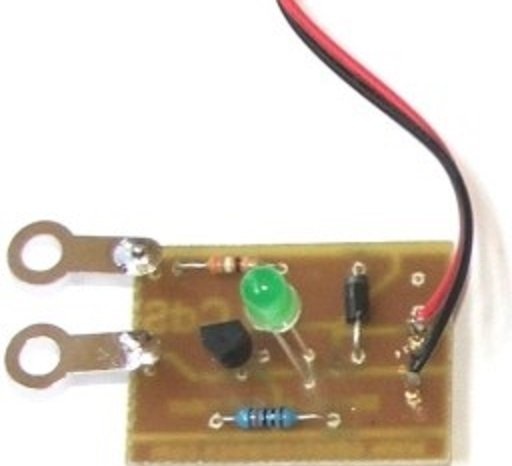
The scheme is very simple. The star resistor is selected depending on the controlled current; it can be from 0.4 to 10 ohms. To charge a lithium-ion battery, I used 4.7 ohms.Current flows through this resistor (if it flows), according to Ohm's law, a voltage is released across it, which opens the transistor. As a result, it lights up Light-emitting diode, indicating charging in progress. As soon as the battery is charged, the internal controller will turn off the battery and the current in the circuit will disappear. The transistor will turn off and Light-emitting diode will go out, thereby making it clear that charging is complete.
Diode VD1 limits the voltage to 0.6 V. You can take any, for a current of 1 A. Again, it all depends on your load. But you can’t use a Schottky diode, since its drop is too small - the transistor simply may not open from 0.4 V. You can even charge car batteries through such a circuit, the main thing is to choose a diode with a current higher than the desired charging current.
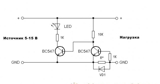
In this example Light-emitting diode turns on while current is passing, but what if you need to show it when there is no current? For this case, there is a circuit with reverse logic.
Everything is the same, only an inverting switch is added on one transistor of the same brand. By the way, a transistor of any same structure. Domestic analogues are suitable - KT315, KT3102.
In parallel with the resistor with the LED, you can turn on a buzzer, and when, when monitoring, say, a light bulb, there is no current, a sound signal will sound. Which will be very convenient, and you won’t have to take it out Light-emitting diode not a control panel.
In general, there can be many ideas for where to use this indicator.
Another example. Let’s say there is some kind of incandescent lamp in a car that you don’t see and don’t know whether it’s on or has burned out. You can also include a current indicator in the circuit to this lamp and monitor the flow. If the lamp burns out, it will be immediately visible.
Or there is some kind of sensor with a filament. Tapa gas or oxygen sensor. And you need to know for sure that the filament has not broken and everything is working properly. This is where the indicator comes to the rescue, the diagram of which I will give below.
There can be a lot of applications, of course the main idea is the same - monitoring the presence of current.
Current indicator circuit
The scheme is very simple. The star resistor is selected depending on the controlled current; it can be from 0.4 to 10 ohms. To charge a lithium-ion battery, I used 4.7 ohms.Current flows through this resistor (if it flows), according to Ohm's law, a voltage is released across it, which opens the transistor. As a result, it lights up Light-emitting diode, indicating charging in progress. As soon as the battery is charged, the internal controller will turn off the battery and the current in the circuit will disappear. The transistor will turn off and Light-emitting diode will go out, thereby making it clear that charging is complete.
Diode VD1 limits the voltage to 0.6 V. You can take any, for a current of 1 A. Again, it all depends on your load. But you can’t use a Schottky diode, since its drop is too small - the transistor simply may not open from 0.4 V. You can even charge car batteries through such a circuit, the main thing is to choose a diode with a current higher than the desired charging current.

In this example Light-emitting diode turns on while current is passing, but what if you need to show it when there is no current? For this case, there is a circuit with reverse logic.
Everything is the same, only an inverting switch is added on one transistor of the same brand. By the way, a transistor of any same structure. Domestic analogues are suitable - KT315, KT3102.
In parallel with the resistor with the LED, you can turn on a buzzer, and when, when monitoring, say, a light bulb, there is no current, a sound signal will sound. Which will be very convenient, and you won’t have to take it out Light-emitting diode not a control panel.
In general, there can be many ideas for where to use this indicator.
Similar master classes
Particularly interesting
Comments (9)

