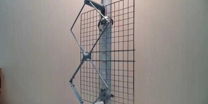
DVB-T2 digital television antenna
Television today is in every home. With the development of technology, the quality of television signals and methods of their transmission change. And if just yesterday antediluvian analogue broadcasting was used, today exclusively digital broadcasting is persistently discussed.
In Russia, television and radio broadcasting is carried out by the state company RTRS. Since 2012, DVB-T2, a multiplex digital broadcasting standard, has been recognized by government decree as a unified standard for digital terrestrial television. The RTRS company, as the only broadcast operator, offers two multiplex packages (RTRS-1 and RTRS-2) for free viewing. All you need is a modern receiver-antenna, one of the options of which today we propose to make with your own hands.
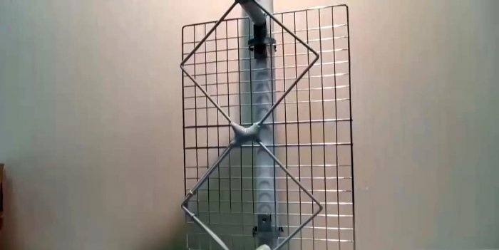
This homemade product is based on the development of engineer Kharchenko K.P., who proposed similar antennas for the decimeter range (DCV), popular in the 90s of the last century. This is similar to aperture antennas, based on a zigzag-shaped feed. The signal is accumulated by a flat reflector, which is at least 20% larger in size than the vibrator.
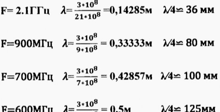
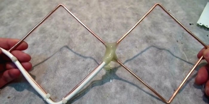
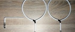
The television signal is transmitted by waves with horizontal polarization. In a simplified form, such an antenna consists of two horizontal loop vibrators connected to each other in parallel, but disconnected at the feeder (cable) connection point. Overall dimensions are given on the basis of Kharchenko’s article “Antenna of the DCV range”, and are calculated according to the proposed formulas. According to this technology, such antennas can be designed even for a weak signal of about 500 MHz.
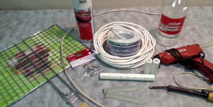
Materials:
Tools:
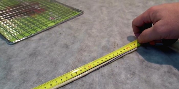
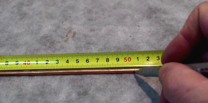
We measure the required length of copper wire with a margin of about 1 cm. You can also use a copper or aluminum tube with a diameter of up to 12 mm.
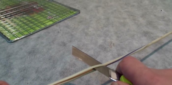
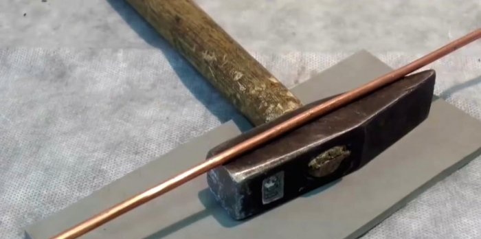
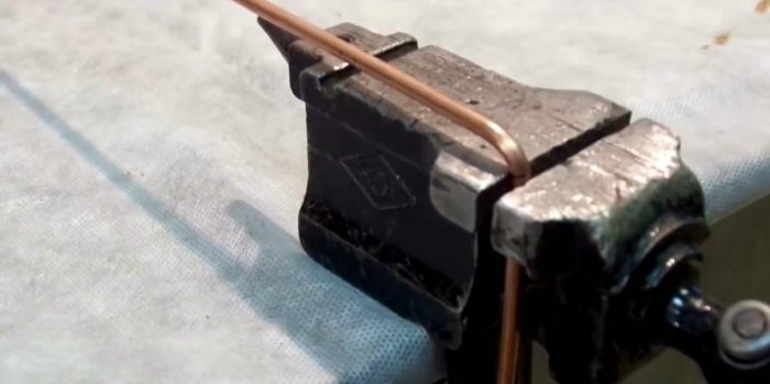
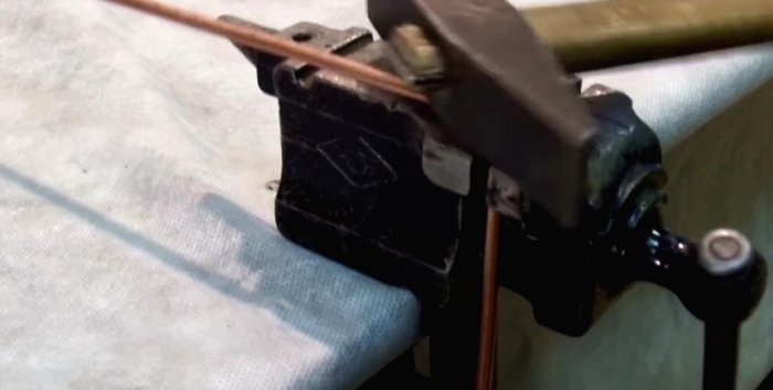
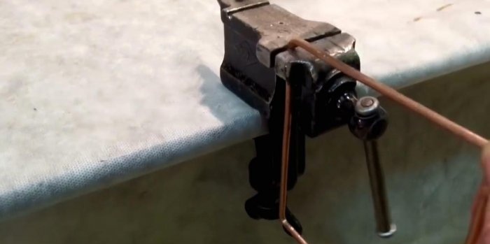
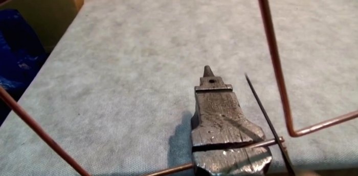
We clear the copper core from the insulation and level it with a hammer on a hard surface. Mark the middle and make a 90° bend. The most accurate way to do this is in a vice, lightly pressing the copper core and leveling it with a hammer.
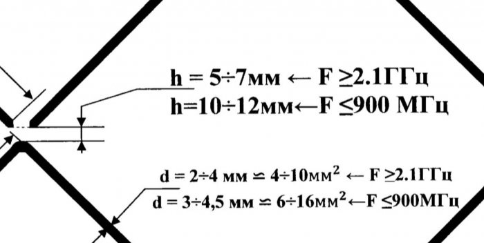
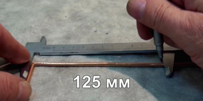
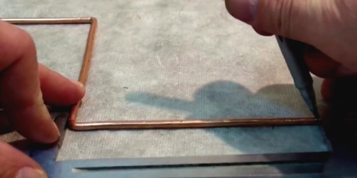
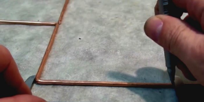
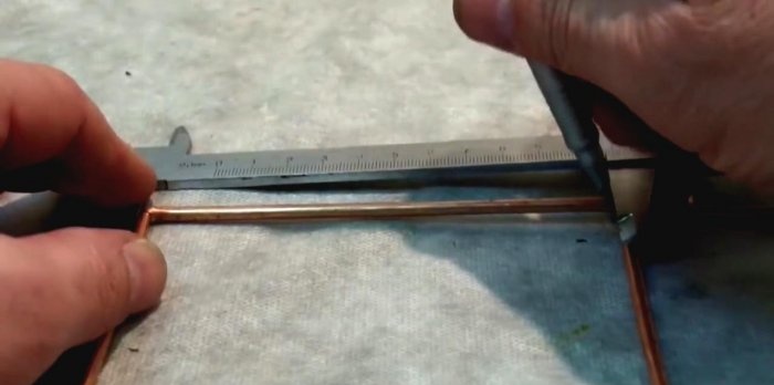
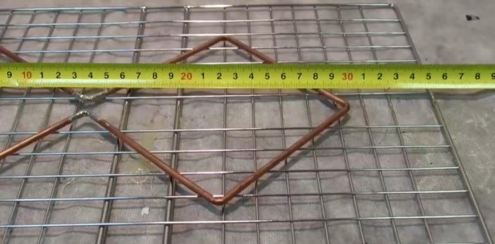
According to our calculations, the sides of the squares will be 125 mm. We mark them with a tape measure and make bends.
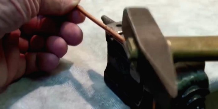
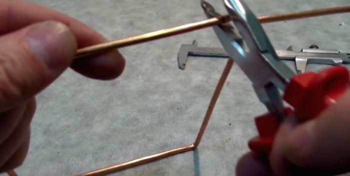
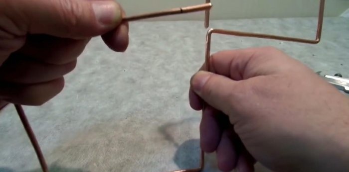
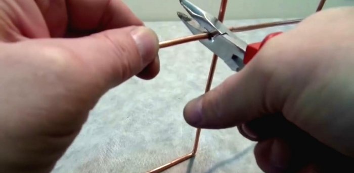
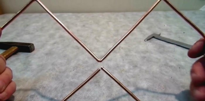
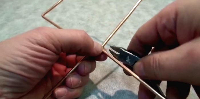
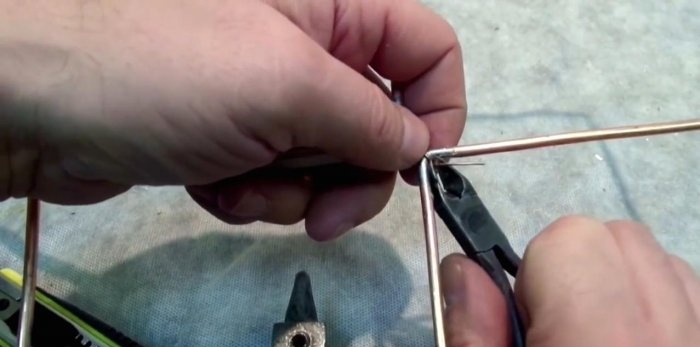
Using side cutters, we bite off a small fragment from one end, making the tip pointed at 45°. After bending the second square, we carry out the same procedure, biting off the final end of the core.The squares can be slightly bent for this purpose.
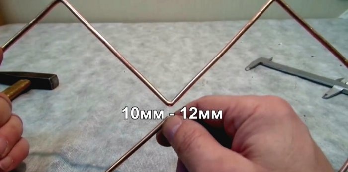
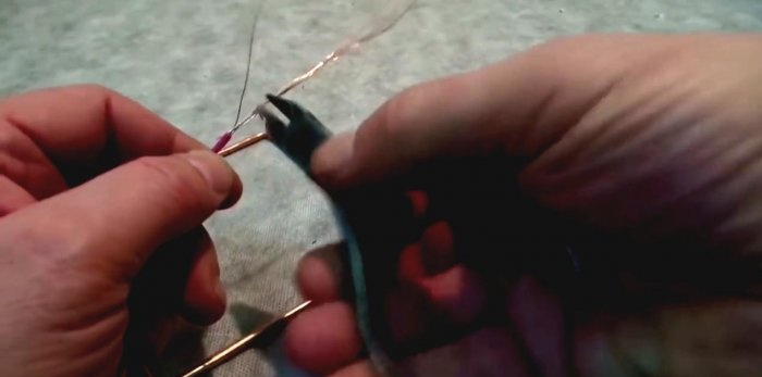
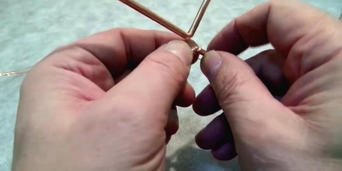
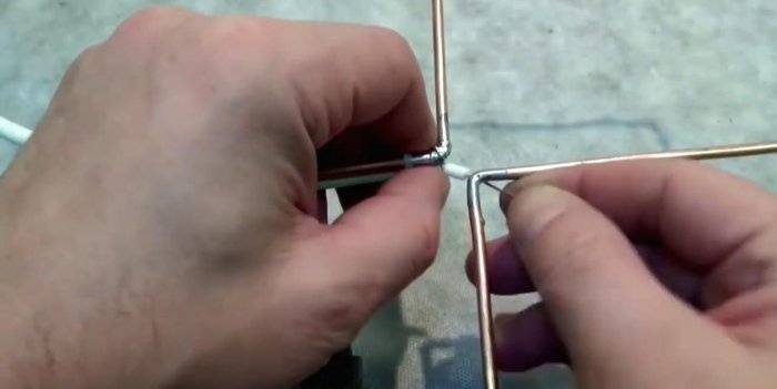
On the middle bends of the squares we achieve a distance of 10-12 mm. At the ends we make shallow cuts with a needle file. This will help us pull both free ends together and secure them with thin copper wire.
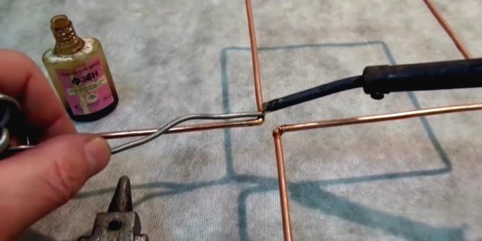
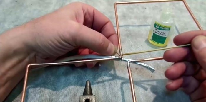
Using liquid rosin or flux, we tin the middle bends with a soldering iron. This must be done on all sides of the copper core of the vibrator.
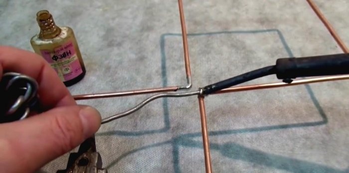
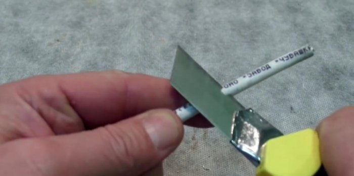
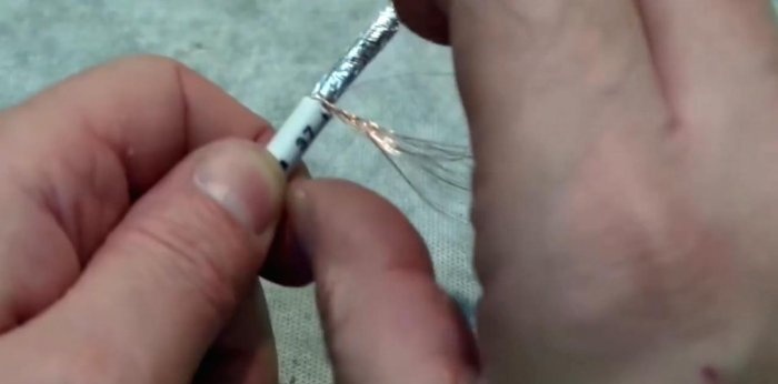
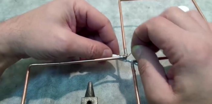
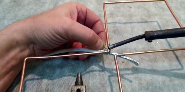
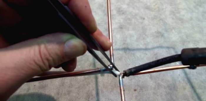
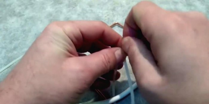
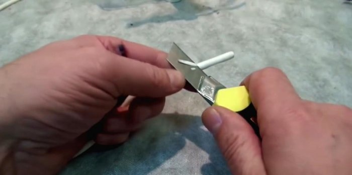
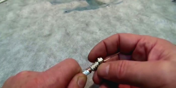
We strip the coaxial cable by 4-5 cm. We twist the braid or outer conductor into a single wire and wrap it around one of the bends. We solder it to the copper core with a soldering iron.
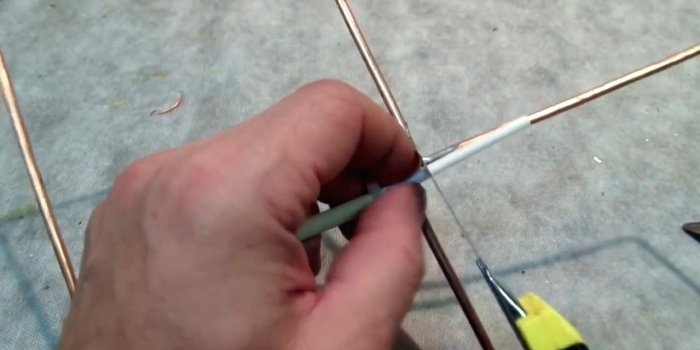
We strip the insulation of the inner conductor and also wrap it around the next bend of the frame. You need to solder it carefully, holding the insulation with pliers, since the temperature can simply move it away from the center. We first heat the frame in the soldering zone, and only then the conductor itself.
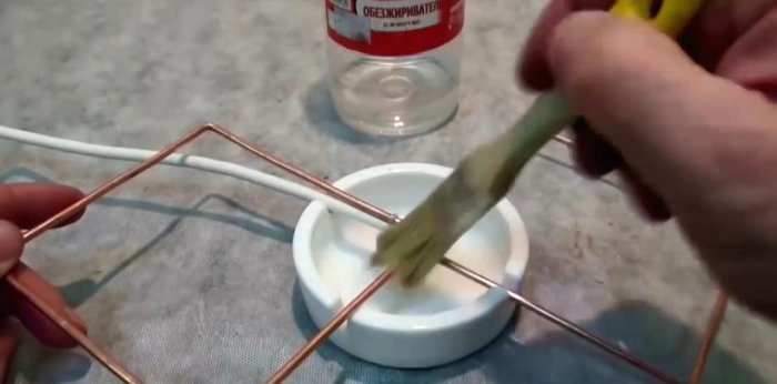
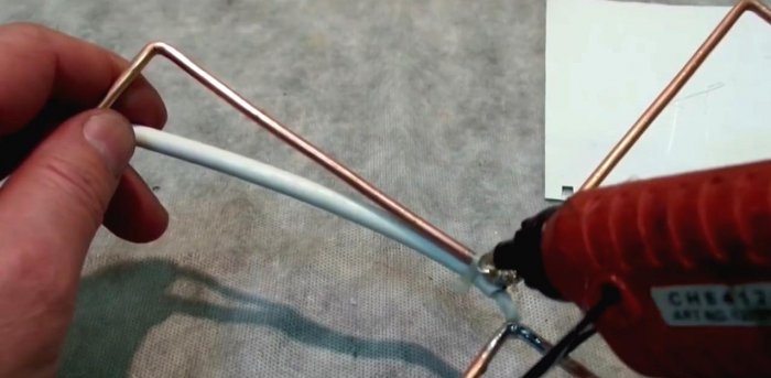
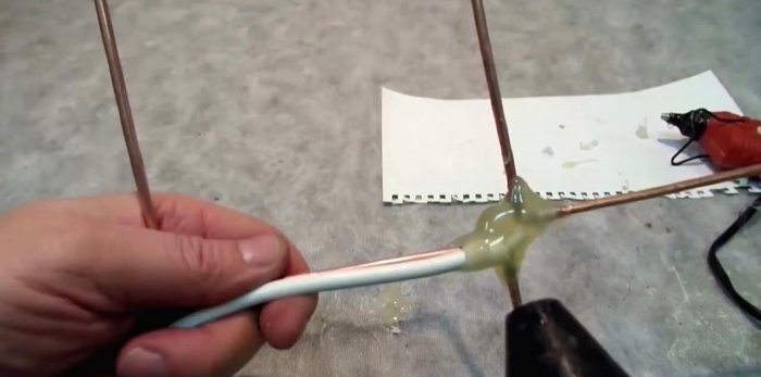
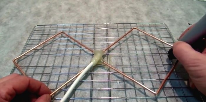
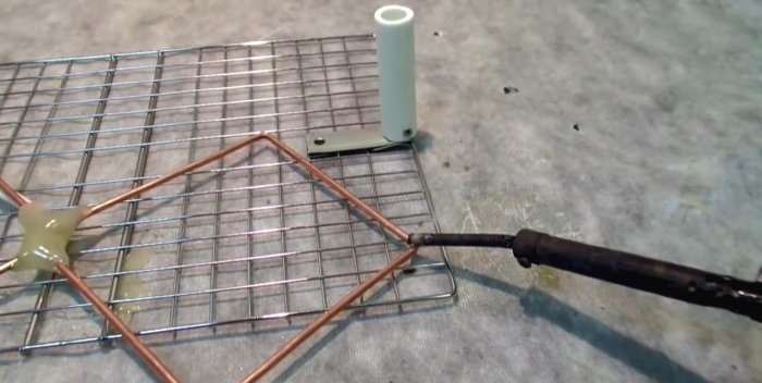
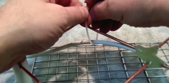
We fix the coaxial cable connection with a nylon tie, degrease it with a solvent and isolate the soldering points with hot glue using a gun. You can correct defects in the resulting cast form of glue with a hairdryer.
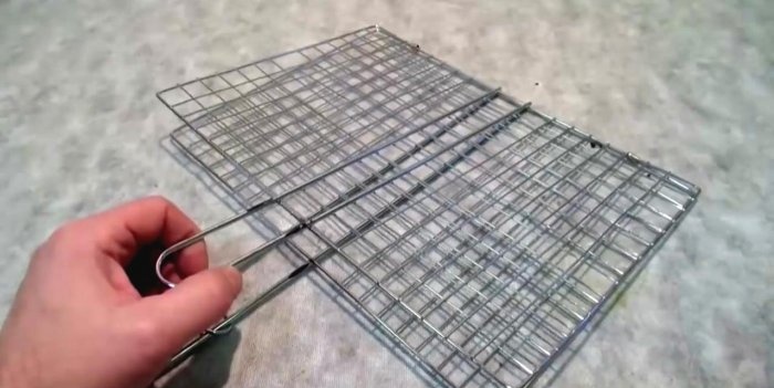
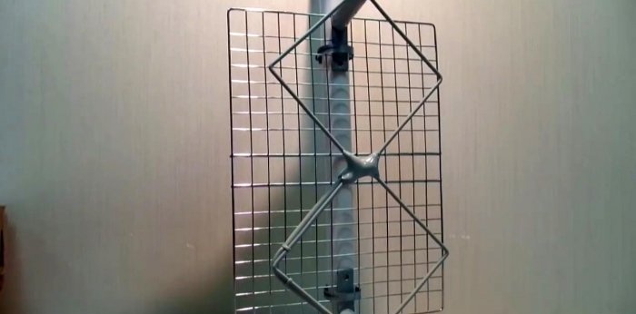
We use an inexpensive barbecue net as a reflector or reflective screen. This is a good material, since even steel samples of such products are covered with a corrosion-resistant anodized coating, not to mention stainless steel. A heat exchanger from a modern refrigerator or a dish drying rack would also be suitable. The main thing is that this element, if possible, does not rust in the air.
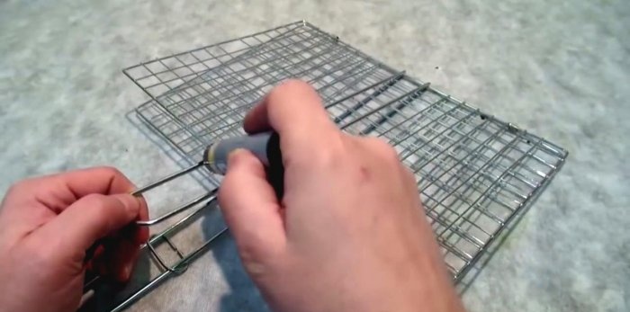
The reflector grid must be larger than the vibrator frame, but does not have to be symmetrical. We cut off the handles from the grille; they will be superfluous in our design.
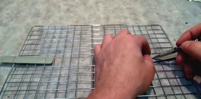
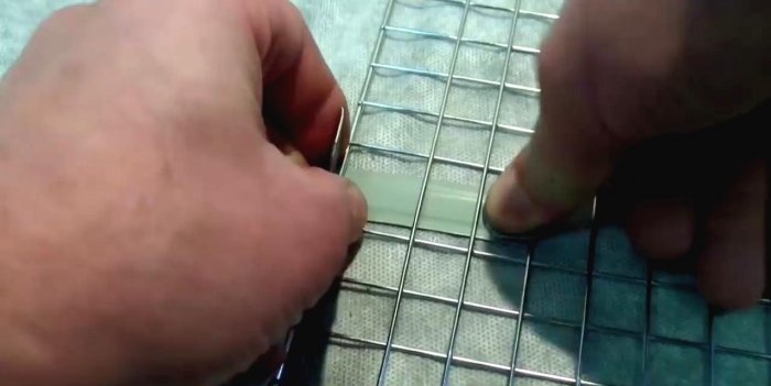
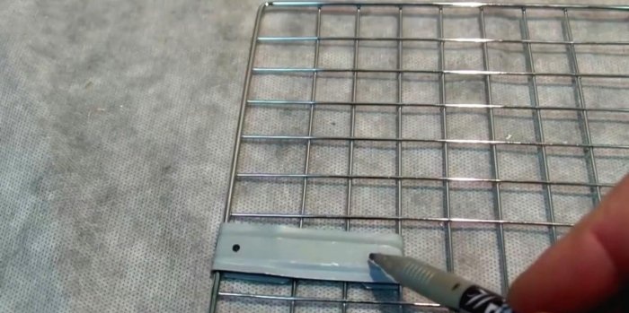
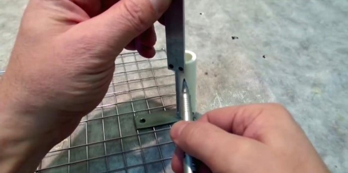
We place the antenna frame in the middle of the reflector and mark its mounting locations.For fastening, you can use two plates of any metal. We bend them along the grid and drill holes with a diameter of 5 mm.
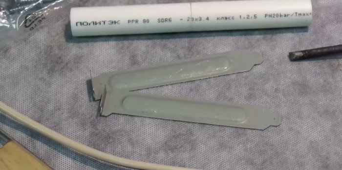
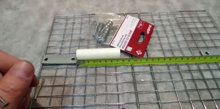
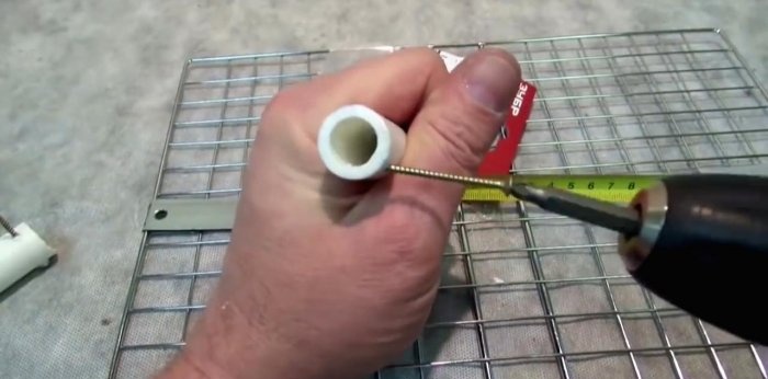
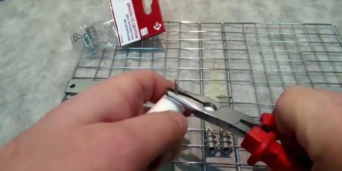
We cut two pieces of PVC pipe 75 mm long, and screw a self-tapping screw into the end of each, cutting off the protruding parts. We break off the pointed ends of the plasterboard dowels and screw them into the opposite end of the tubes.
We screw both PVC stands to the strips on the reflector with self-tapping screws. We tin the frame at the ends suitable for the racks for better heat transfer.
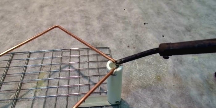
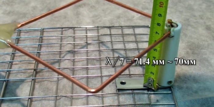
On the racks we mark the height of 68 mm, and put it at risk. We heat the ends of the frame with a soldering iron and solder them into the racks to the required marks.
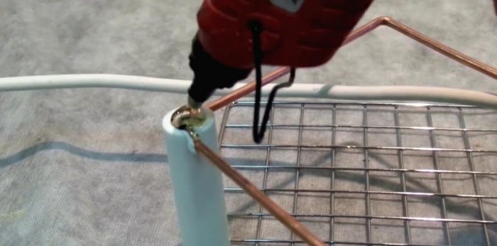
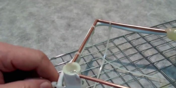
We fill the ends of the stands with hot glue, securely fixing the vibrator frame at their base. We determine the position of the cable relative to the installation of the antenna, and fix it on the frame with nylon ties.
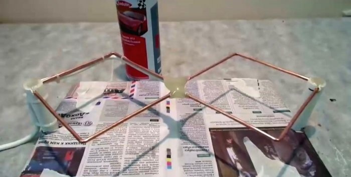
Since oxidation degrades the quality of the received signal, the reflector frame must be protected. This is not at all difficult to do using spray paint.
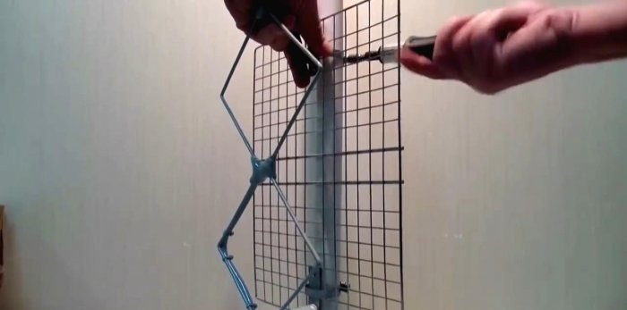
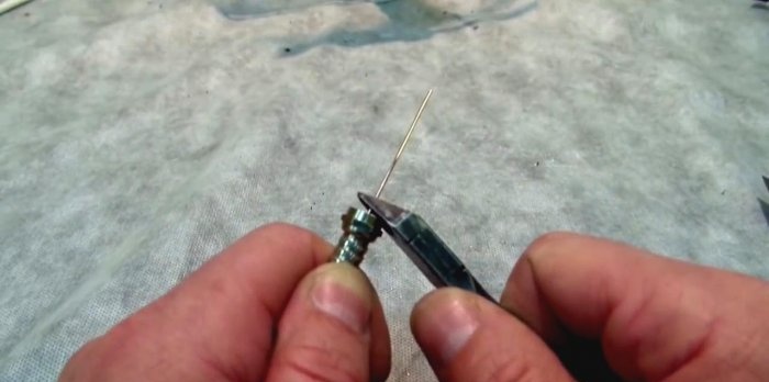
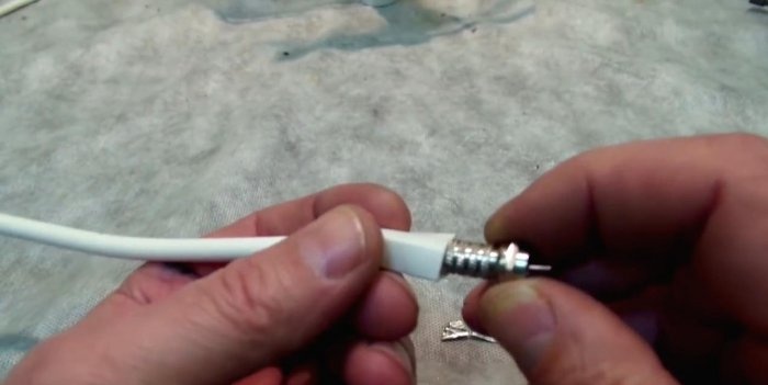
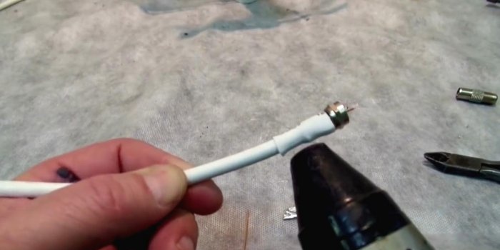
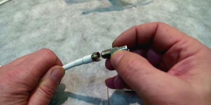
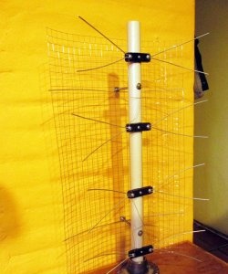
Since our screen is lattice, it is very easy to attach the finished antenna to a mast or pipe section using clamps. At the opposite end of the TV cable we mount a standard TV connector F. We close it for insulation with a heat-shrinkable casing and warm it up.
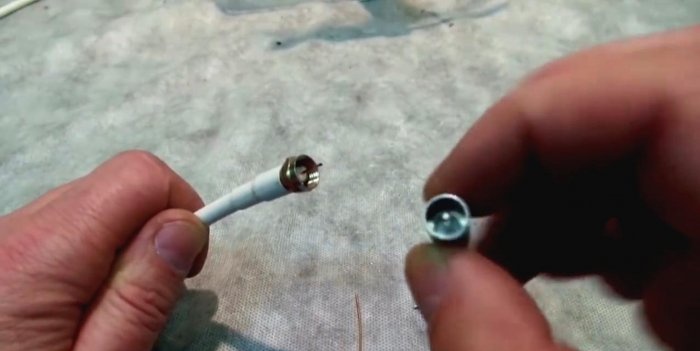
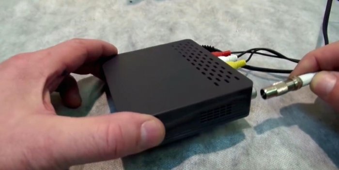
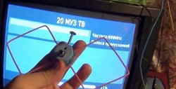
We screw the TV plug into the connector. We connect the cable to a digital television receiver or directly to a TV with a digital tuner, and enjoy free viewing of TV channels in digital quality.
Such an antenna should, if possible, be placed towards the repeater. To enhance signal reception, the vibrator frame is supplemented with several “squares”, and the reflector grid is complicated by horizontal bends.
In Russia, television and radio broadcasting is carried out by the state company RTRS. Since 2012, DVB-T2, a multiplex digital broadcasting standard, has been recognized by government decree as a unified standard for digital terrestrial television. The RTRS company, as the only broadcast operator, offers two multiplex packages (RTRS-1 and RTRS-2) for free viewing. All you need is a modern receiver-antenna, one of the options of which today we propose to make with your own hands.
This homemade product is based on the development of engineer Kharchenko K.P., who proposed similar antennas for the decimeter range (DCV), popular in the 90s of the last century. This is similar to aperture antennas, based on a zigzag-shaped feed. The signal is accumulated by a flat reflector, which is at least 20% larger in size than the vibrator.
The television signal is transmitted by waves with horizontal polarization. In a simplified form, such an antenna consists of two horizontal loop vibrators connected to each other in parallel, but disconnected at the feeder (cable) connection point. Overall dimensions are given on the basis of Kharchenko’s article “Antenna of the DCV range”, and are calculated according to the proposed formulas. According to this technology, such antennas can be designed even for a weak signal of about 500 MHz.
What is needed to assemble the antenna
Materials:
- Barbecue grill;
- Aerosol paint for cars;
- Solvent or acetone;
- A set of drills for a conventional drill;
- Coaxial television cable – no more than 10 m;
- Half a meter of HV PVC pipe, diameter – 20 mm;
- Metal dowels for drywall;
- Copper wire for the antenna vibrator, core diameter – 2-3.5 mm;
- Two thin metal plates.
Tools:
- Soldering iron powerful 100 W;
- Screwdriver with attachments;
- Hot glue gun;
- Pliers, hammer, wire cutters;
- Painting knife, tape measure, pencil.
Let's start making the antenna
Making a vibrator frame
We measure the required length of copper wire with a margin of about 1 cm. You can also use a copper or aluminum tube with a diameter of up to 12 mm.
We clear the copper core from the insulation and level it with a hammer on a hard surface. Mark the middle and make a 90° bend. The most accurate way to do this is in a vice, lightly pressing the copper core and leveling it with a hammer.
According to our calculations, the sides of the squares will be 125 mm. We mark them with a tape measure and make bends.
Using side cutters, we bite off a small fragment from one end, making the tip pointed at 45°. After bending the second square, we carry out the same procedure, biting off the final end of the core.The squares can be slightly bent for this purpose.
On the middle bends of the squares we achieve a distance of 10-12 mm. At the ends we make shallow cuts with a needle file. This will help us pull both free ends together and secure them with thin copper wire.
Using liquid rosin or flux, we tin the middle bends with a soldering iron. This must be done on all sides of the copper core of the vibrator.
We strip the coaxial cable by 4-5 cm. We twist the braid or outer conductor into a single wire and wrap it around one of the bends. We solder it to the copper core with a soldering iron.
We strip the insulation of the inner conductor and also wrap it around the next bend of the frame. You need to solder it carefully, holding the insulation with pliers, since the temperature can simply move it away from the center. We first heat the frame in the soldering zone, and only then the conductor itself.
We fix the coaxial cable connection with a nylon tie, degrease it with a solvent and isolate the soldering points with hot glue using a gun. You can correct defects in the resulting cast form of glue with a hairdryer.
Preparing the reflector
We use an inexpensive barbecue net as a reflector or reflective screen. This is a good material, since even steel samples of such products are covered with a corrosion-resistant anodized coating, not to mention stainless steel. A heat exchanger from a modern refrigerator or a dish drying rack would also be suitable. The main thing is that this element, if possible, does not rust in the air.
The reflector grid must be larger than the vibrator frame, but does not have to be symmetrical. We cut off the handles from the grille; they will be superfluous in our design.
We place the antenna frame in the middle of the reflector and mark its mounting locations.For fastening, you can use two plates of any metal. We bend them along the grid and drill holes with a diameter of 5 mm.
Assembling the antenna
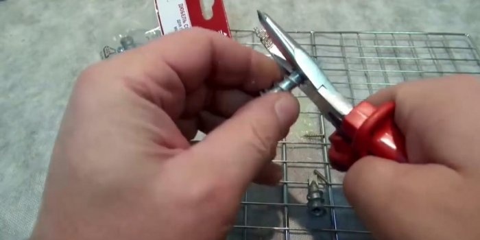
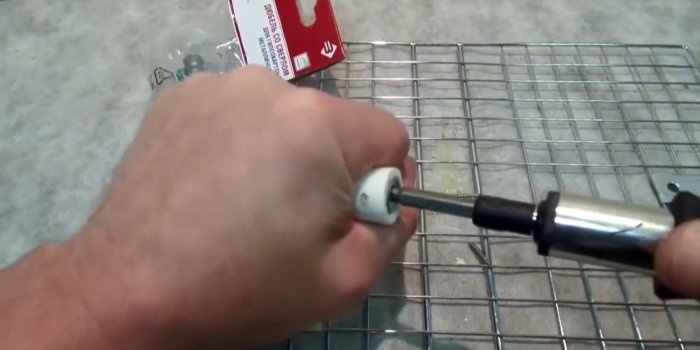
We cut two pieces of PVC pipe 75 mm long, and screw a self-tapping screw into the end of each, cutting off the protruding parts. We break off the pointed ends of the plasterboard dowels and screw them into the opposite end of the tubes.
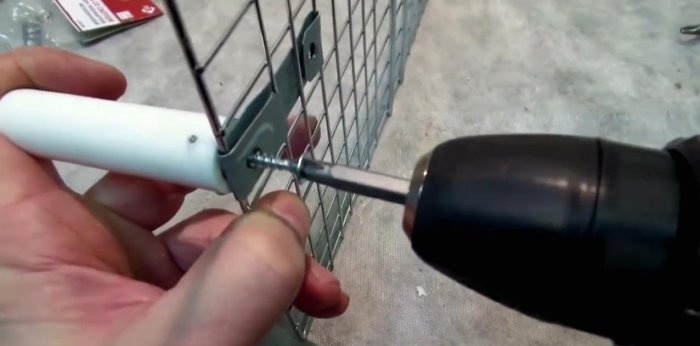
We screw both PVC stands to the strips on the reflector with self-tapping screws. We tin the frame at the ends suitable for the racks for better heat transfer.
On the racks we mark the height of 68 mm, and put it at risk. We heat the ends of the frame with a soldering iron and solder them into the racks to the required marks.
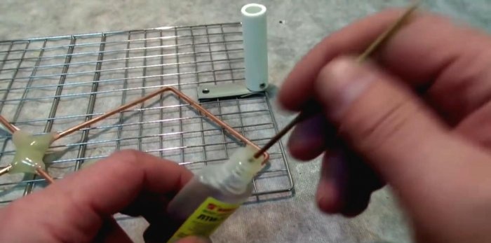
We fill the ends of the stands with hot glue, securely fixing the vibrator frame at their base. We determine the position of the cable relative to the installation of the antenna, and fix it on the frame with nylon ties.
Since oxidation degrades the quality of the received signal, the reflector frame must be protected. This is not at all difficult to do using spray paint.
Since our screen is lattice, it is very easy to attach the finished antenna to a mast or pipe section using clamps. At the opposite end of the TV cable we mount a standard TV connector F. We close it for insulation with a heat-shrinkable casing and warm it up.
We screw the TV plug into the connector. We connect the cable to a digital television receiver or directly to a TV with a digital tuner, and enjoy free viewing of TV channels in digital quality.
Such an antenna should, if possible, be placed towards the repeater. To enhance signal reception, the vibrator frame is supplemented with several “squares”, and the reflector grid is complicated by horizontal bends.
Watch a video on making a DVB-T2 television antenna
Similar master classes
Particularly interesting
Comments (9)

