Hidden wiring detector
Quite often, residents of apartment buildings need to attach a picture, hanger, shelf or some other piece of furniture to the wall of their apartment. To do this, you need to mark a point on the wall and drill a small hole with a hammer drill. However, there is always the possibility of getting caught in the wiring hidden in the wall under the wallpaper - in this case, a small renovation of the interior may result in the inevitable call to the electricians. To prevent this from happening, you can assemble a simple hidden wiring detector that will show exactly where the wires are and where they are not.
Scheme
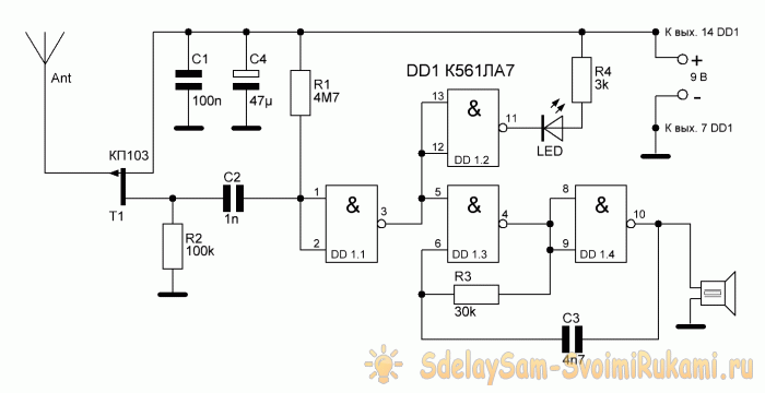
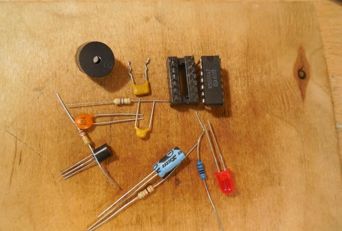
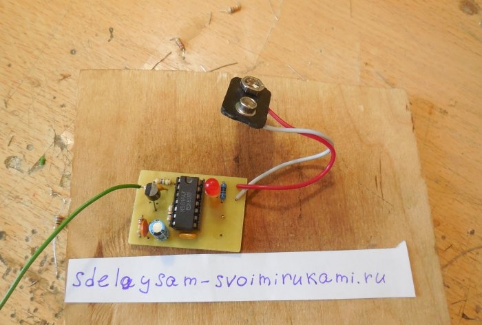
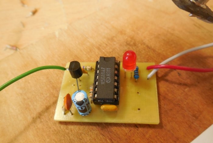
The sensitive element of the circuit is a field-effect transistor KP103, to the gate of which an antenna is connected. You can use a transistor in any package and with any letter index. The device reacts to wires under voltage of 220 V 50 Hz, regardless of whether current flows through them or not. The circuit also uses the K561LA7 microcircuit, which consists of 4 2I-NOT logic elements. It can be replaced with an imported analogue, the CD4011 microcircuit. Light-emitting diode in the diagram it lights up when the antenna is in close proximity to a live wire.As an antenna, you can use a piece of ordinary thin wire, 5-10 cm long. The longer its length, the greater the sensitivity of the device. The circuit consumes approximately 10-15 mA and is powered by a voltage of 9 volts. A regular Krona battery is suitable for power supply. If necessary, any piezoceramic emitter, for example, ZP-3, can be connected to pin 10 of the microcircuit, then a sound will be heard when a wire is detected.
You can download the board here:Detector assembly
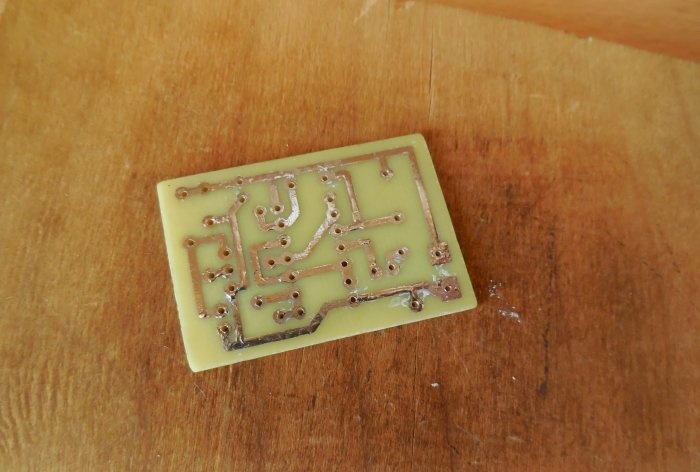
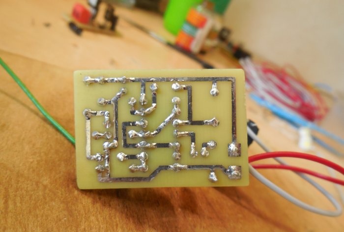
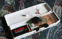
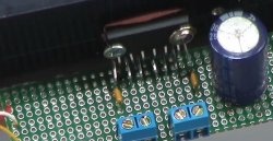
The circuit is assembled on a miniature printed circuit board measuring 40 x 30 mm, which can be made using the LUT method. The printed circuit board is completely ready for printing; there is no need to mirror it. After etching, it is advisable to tin the tracks; this will simplify the soldering of parts, and the copper will not oxidize.
After manufacturing the printed circuit board, you can solder the parts. You should be careful when handling the microcircuit - it is sensitive to static and can be easily damaged. Therefore, we solder the socket for the microcircuit onto the board and place the microcircuit in it only after the assembly is completed. You also need to be careful when soldering the transistor - if it is in a plastic case, then only two legs are soldered onto the board - drain and source, and the antenna is soldered directly to the gate. If the case is metal, all three legs are soldered onto the board along with the antenna. It is important not to mix up the pinout, otherwise the device will not work. For convenience, the power wires can be immediately soldered to the connector for Krona, as I did. After completing soldering, be sure to wash off any remaining flux from the board, otherwise sensitivity may be affected. It is also advisable to check the correct installation and adjacent tracks for short circuits.
Detector tests
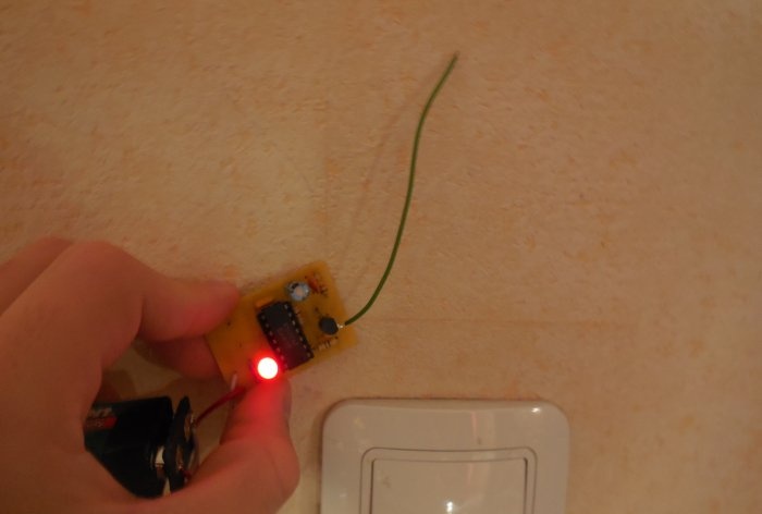
After assembly is completed, testing can begin. We take the crown and connect it to the board, placing an ammeter in the gap of one of the wires. The circuit consumption should be 10-15 mA. If the current is normal, you can bring the detector antenna to any network wire and watch how it lights up Light-emitting diode and beep the piezo emitter, if installed. The wire detection range is approximately 3-5 cm, depending on the length of the antenna. In this case, you should not touch the antenna, as this will significantly reduce the sensitivity. The device does not require any setup and starts working immediately after power is applied. In addition to network wires, it also responds to twisted pair cable. Happy assembly.
Watch the video
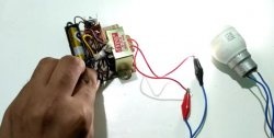
The video clearly shows how such a detector works. With its help, you can accurately determine where the wires from the switch run.

