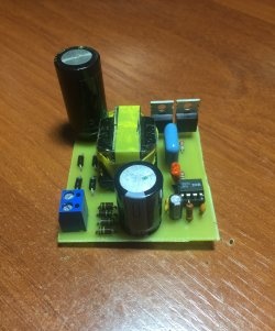
The simplest transformerless power supply for an LED matrix
Many LED bulbs and spotlights require 12V to power them, which requires you to buy or obtain a power source from somewhere. In fact, you can make it yourself using inexpensive parts.
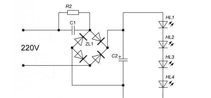
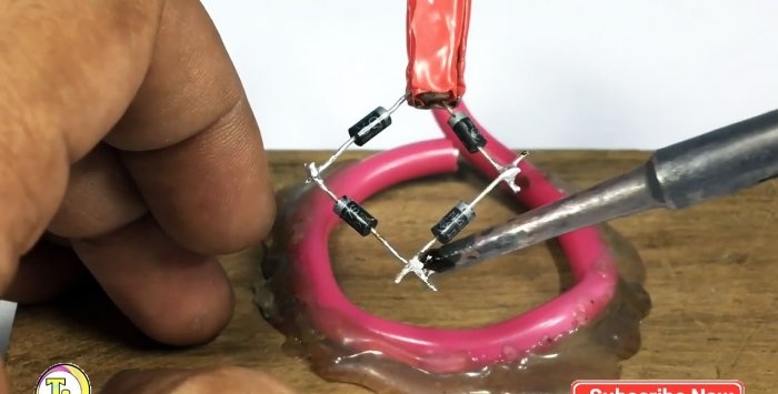
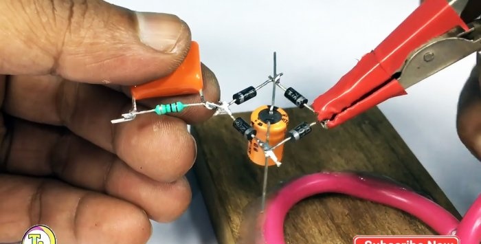
First you need to solder 4 1N4007 diodes together, according to the circuit as in the photo. Pay attention to the polarity. It is important that the direction of the anode and cathode are as in the photograph. Beginning radio enthusiasts just need to follow the gray strip around the circumference of the diode body. As you can see, one pair of them is connected stripe to stripe, and the second with dark sides. Accordingly, the pairs are soldered together by a strip to the plain side.
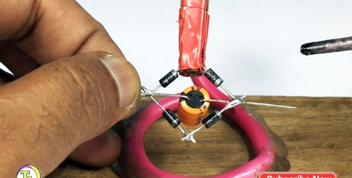
For a 220 uF 25 V capacitor, you need to bend the contacts and solder them to a frame of diodes. There is a longitudinal stripe on its body.The electrode opposite to it is soldered to the contacts of the diodes connected strip to strip. The contact adjacent to the mark is fastened accordingly to the diodes on the side opposite to the stripes.
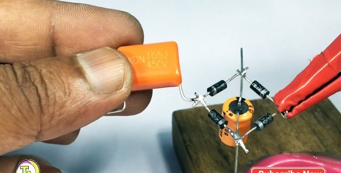
Next, a 1 µF ceramic capacitor (105J) is soldered to the existing circuit with one tendril. To do this, it should be placed on the left hand and turned with the marking towards you.
A 1 MΩ resistor is soldered between the antennae of the ceramic capacitor. It has no polarity, so it can be placed on either side. This resistor is needed to discharge the capacitor when power is disconnected from the entire circuit.
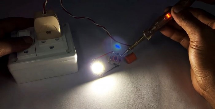
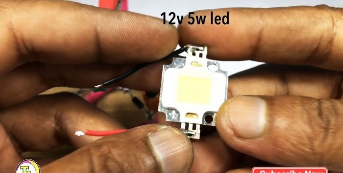
The consumer is connected to the circuit. In this case, a 12 V and 5 W LED matrix is used.
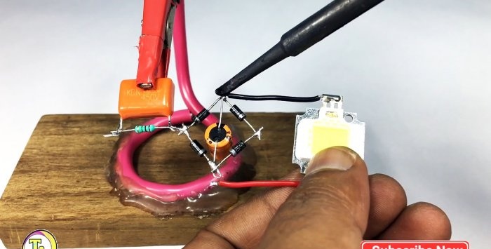
In order for it to shine, you need to maintain the polarity. The minus is connected to the electrodes on the side of the strip on a 220 uF 25 V capacitor. The plus is soldered opposite.
To power the circuit from a 220V network, you need to connect a two-core cable with a plug. One core is soldered to the electrode of a ceramic capacitor and resistor, and the second to the unused opposite part of the diode frame.
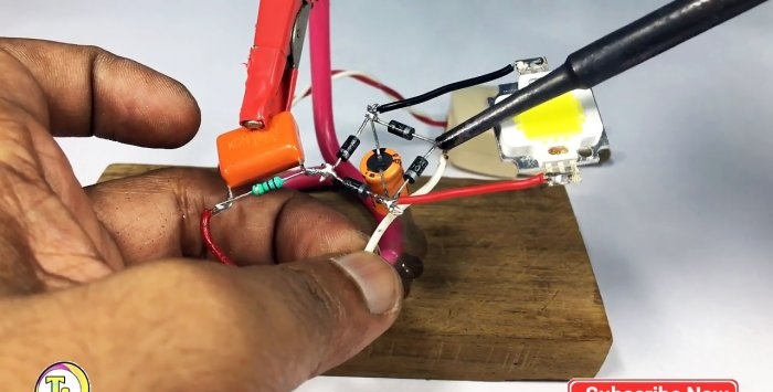
We plug it into the network.
Works great.
This is a very cheap power source to manufacture. LEDs and their matrices, but it has one very significant drawback: you cannot touch it so as not to receive a 220 V discharge, since the entire circuit does not have galvanic isolation. Therefore, this homemade product may not be suitable for everyone.
The finished source must be placed in a box made of dielectric material. During operation, it is forbidden to even touch the LED matrix; be sure to take this into account.
Materials:
- LED Matrix 12V 5W.
- 4 diodes 1N4007;
- ceramic capacitor 1 μF, voltage not lower than 400 V;
- 1 resistor in the range of 300 kOhm - MOhm;
- capacitor 220 uF 25 V;
- electrical cable with plug.
Assembly of a transformerless source

First you need to solder 4 1N4007 diodes together, according to the circuit as in the photo. Pay attention to the polarity. It is important that the direction of the anode and cathode are as in the photograph. Beginning radio enthusiasts just need to follow the gray strip around the circumference of the diode body. As you can see, one pair of them is connected stripe to stripe, and the second with dark sides. Accordingly, the pairs are soldered together by a strip to the plain side.
For a 220 uF 25 V capacitor, you need to bend the contacts and solder them to a frame of diodes. There is a longitudinal stripe on its body.The electrode opposite to it is soldered to the contacts of the diodes connected strip to strip. The contact adjacent to the mark is fastened accordingly to the diodes on the side opposite to the stripes.
Next, a 1 µF ceramic capacitor (105J) is soldered to the existing circuit with one tendril. To do this, it should be placed on the left hand and turned with the marking towards you.
A 1 MΩ resistor is soldered between the antennae of the ceramic capacitor. It has no polarity, so it can be placed on either side. This resistor is needed to discharge the capacitor when power is disconnected from the entire circuit.
The consumer is connected to the circuit. In this case, a 12 V and 5 W LED matrix is used.
In order for it to shine, you need to maintain the polarity. The minus is connected to the electrodes on the side of the strip on a 220 uF 25 V capacitor. The plus is soldered opposite.
To power the circuit from a 220V network, you need to connect a two-core cable with a plug. One core is soldered to the electrode of a ceramic capacitor and resistor, and the second to the unused opposite part of the diode frame.
We plug it into the network.
Works great.
Important! Safety precautions
This is a very cheap power source to manufacture. LEDs and their matrices, but it has one very significant drawback: you cannot touch it so as not to receive a 220 V discharge, since the entire circuit does not have galvanic isolation. Therefore, this homemade product may not be suitable for everyone.
The finished source must be placed in a box made of dielectric material. During operation, it is forbidden to even touch the LED matrix; be sure to take this into account.
Watch the video
Similar master classes
Particularly interesting

Cable antenna for digital TV in 5 minutes
A selection of simple and effective schemes.

Three-phase voltage from single-phase in 5 minutes
Starting a three-phase motor from a single-phase network without a capacitor

Eternal flashlight without batteries
How to make an inexpensive but very powerful LED lamp
Comments (6)

