How to assemble a circuit to control a load using any remote control
Controlling certain devices or loads using remote control panels is often widely used in both industrial and residential buildings. Often this can be the remote switching on and off of lighting fixtures, air conditioners, hoods, garage doors, etc.
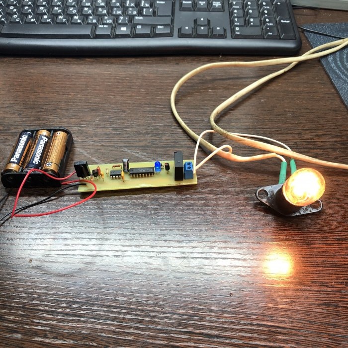
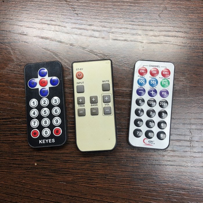
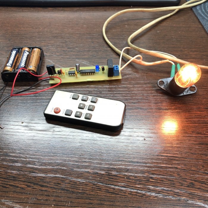
Such devices that turn on or off lighting or other loads at a distance usually consist of a photodetector and an emitting diode operating in the infrared range and usually consist of two parts, the control board itself with an infrared receiver and a remote control. You can easily assemble such a device yourself, the advantage of this circuit is that it does not contain expensive parts and the remote control can be any remote control from an old TV, VCR, etc.
Scheme:
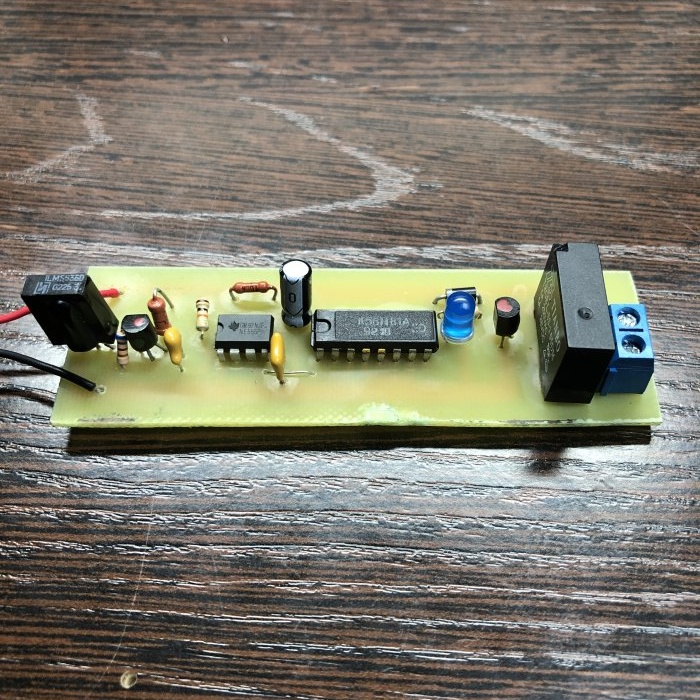
The LMS5360 sensor is used as an IR receiver; it is a three-pin IR receiver that operates at a frequency of 38 KHz. When the sensor detects an IR signal, a logical 0 will be present at the output of the sensor, this signal is very weak, then it is received and amplified by transistor VT1.This signal then goes to the NE555's standby multivibrator and triggers it.
From the output of the microcircuit (pin 3), the signal goes to pin 3 of the K561TV1A microcircuit and switches the trigger, then from the output (pin 1) the signal goes to the base of transistor VT2, which in turn controls the relay. With each signal from the 555 timer, the trigger will change accordingly, the relay will be triggered, thereby turning on or off the load.
The scheme also provides Light-emitting diode HL1 which is provided as an indication to monitor whether the device is turned on or not. With a 5-volt power supply, resistor R5 can be excluded from the circuit, given that if Light-emitting diode designed for supply voltage 2.5-3 volts. In order to prevent the timer from false operation, the circuit contains resistor R4 and capacitor C2.
Diode VD1 is connected in parallel to the relay coil by reverse connection to prevent jumps and bursts of EMF; otherwise, without it, interference may enter the circuit, which has a detrimental effect on low-power transistors and sensitive elements.
About details:
- As an IR sensor, you can use any similar one operating at a frequency of 38 KHz with three pins, as in my case from an old TV, it is important to take into account the pinout of these sensors.
- Resistors with R1-R6 with a power of 0.25 Watt.
- Electrolytic capacitors C1, C3 with a voltage of at least 16 volts C2 ceramic or film 100 nanofarads C4 ceramic or film 10 nanofarads.
- Transistors VT1 VT2 kt3102 or analogues BC184 BC182 2N4123 BC547.
- Light-emitting diode any designed for a voltage of 2.5-3 volts.
- Microcircuit DD2 timer NE555 or domestic analogue KR1006VI1A.
- Microcircuit DD2 CD4027 or domestic analog K561TV1A.
- VD1 rectifier diode Kd522 or imported 1N4004 14007.
- A relay with a coil voltage of 5 volts and the ability to switch current, as in my case 3 amperes, if the needs grow, then install a relay with a high switching current of 5-10 amperes, etc.
You can download the board here:
Pros:
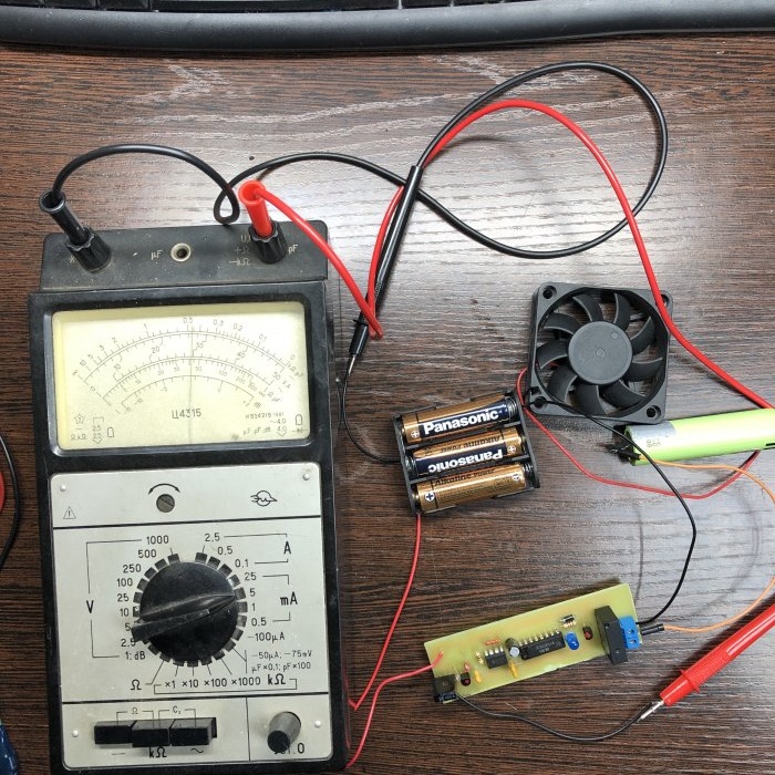
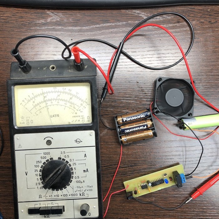
At idle, the device consumes 3 mA, which allows the device to be powered by 3 AA batteries. When operating, the current consumption of the device is about 36-37 Ma.
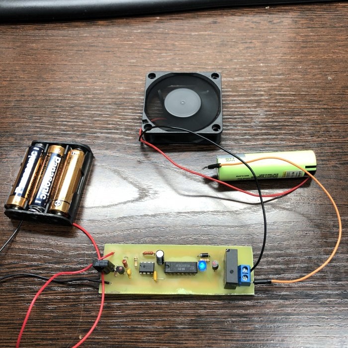
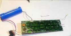
Ability to switch powerful loads from either direct or alternating current 220 volts. The device dimensions are a printed circuit board with dimensions of 9.5 by 3 cm. The range is 10 meters.

