How to organize automatic oil supply for a furnace during mining
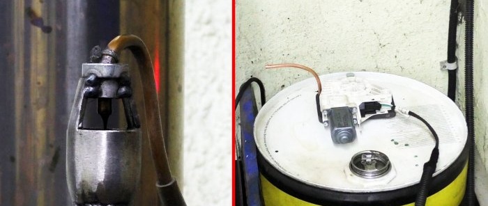
Many people are thinking about making a working stove for a garage or workshop. For its operation, it is necessary to use an oil pump, which will supply fuel to the combustion chamber. Consider how to make such an automatic oil pump with your own hands.
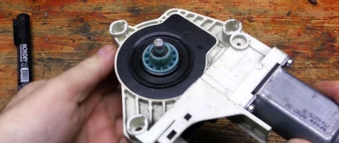
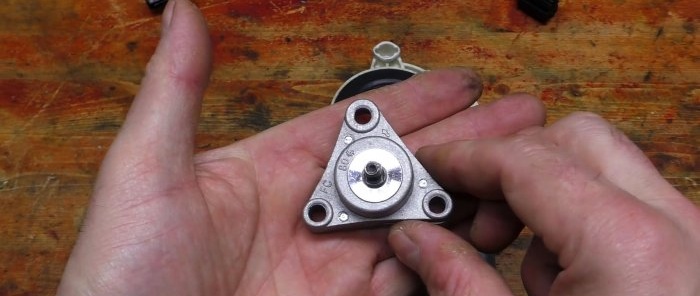
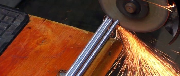
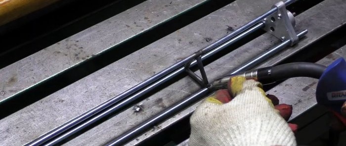
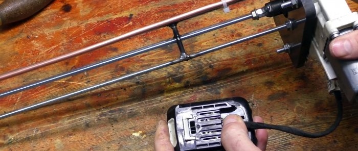
The design involves lowering the oil pump from the scooter into a container with oil. A long shaft will go from it to the surface to the window regulator motor-reducer, which will serve as the electric drive of the system. To implement this, you need to weld a frame from three M6 studs and jumpers, at one end of which the pump will be attached, and at the second an electric motor. For this purpose, the length of the studs must correspond to the depth of the waste container. They are welded in a triangle under the holes on the oil pump.
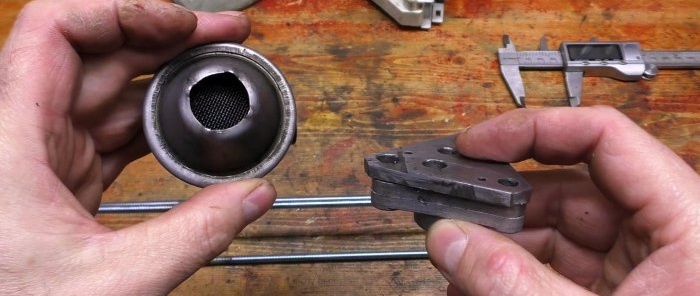
An adapter plate for the oil pump must be cut from thick sheet steel. Holes are drilled in it for oil intake and injection, as well as a frame made of studs. You need to put a mesh on the fence to prevent any shavings present in the mining from getting inside.
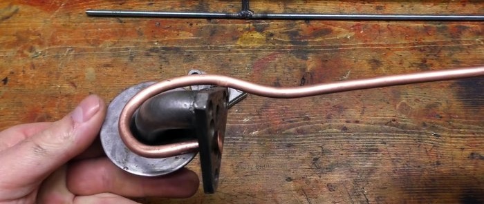
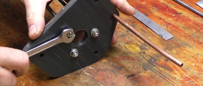
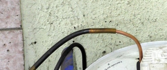
You need to bend the oil supply channel from the 6 mm copper tube. It needs to be flared at one end. It is inserted into the stove. To do this, the hole must have a chamfer. The tube is turned towards the electric drive to exit the container.
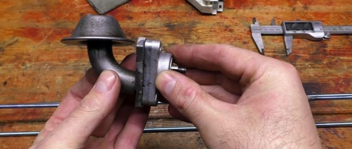
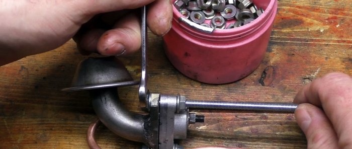
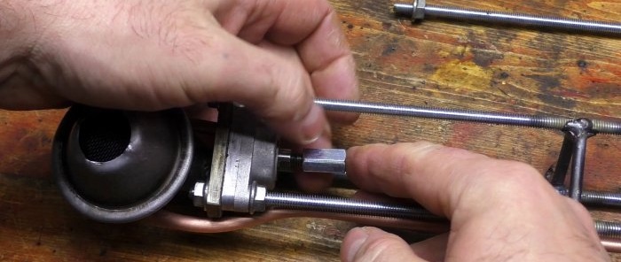
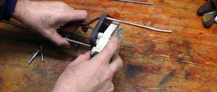
Using nuts, a pump and an adapter plate with a tube are installed and pressed together onto the edge of the frame. An extended nut is screwed onto the oil pump shaft. A pin is screwed into it, which will transmit torque from the gear motor.
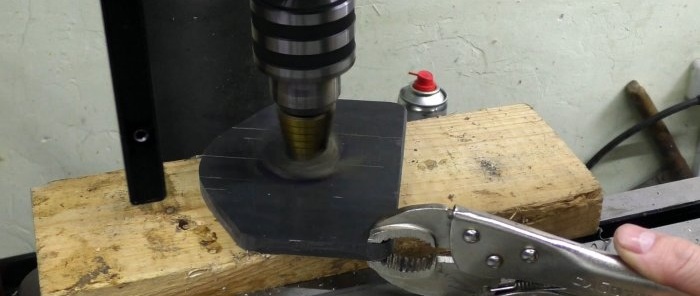
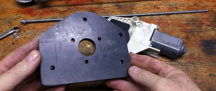
An adapter plate is cut out of thick plastic to attach the gear motor to the frame.
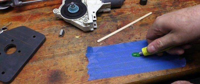
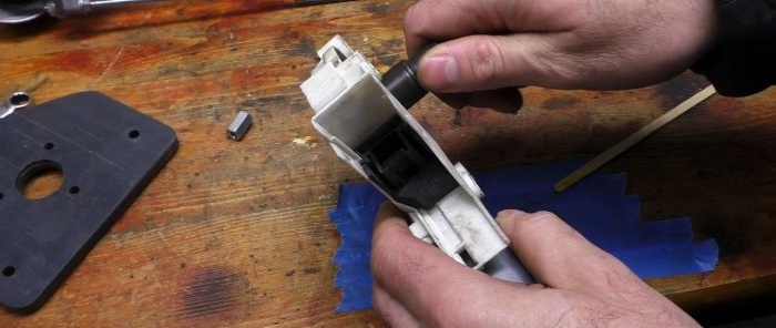
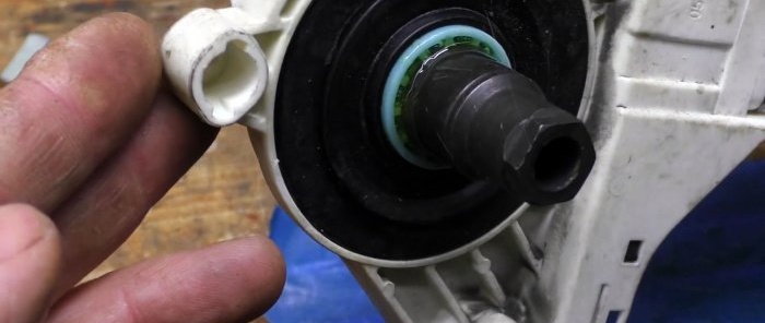
Next, you need to equip the window lift shaft with an adapter for an M6 internal thread in order to connect to the pin coming from the pump. To do this, a tube or part of the nozzle is glued onto its gear with epoxy resin. An extended M6 nut is welded on top of it.
Next, a plastic plate is installed, then the drive itself. The central pin will need to be locked, as it can get unscrewed during rotation. The supply tube is attached to the frame with a tie.
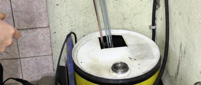
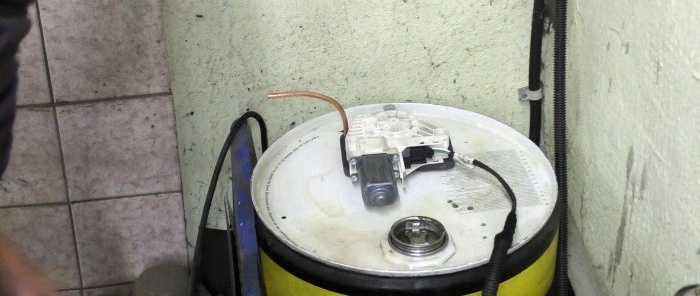
Next, the pump is immersed in a container with processing. It is powered by a 12 V unit through a speed controller, on which the oil pumping speed is set to the power of the stove.
Materials:
- gear motor for window lift -
- scooter oil pump -
- M6 studs – 4 pcs.;
- sheet steel 5-10 mm;
- copper tube 6 mm;
- plastic plate;
- power supply 12V;
- speed controller for engine -
- M6 nuts.
The process of manufacturing a pump for a furnace during development
The design involves lowering the oil pump from the scooter into a container with oil. A long shaft will go from it to the surface to the window regulator motor-reducer, which will serve as the electric drive of the system. To implement this, you need to weld a frame from three M6 studs and jumpers, at one end of which the pump will be attached, and at the second an electric motor. For this purpose, the length of the studs must correspond to the depth of the waste container. They are welded in a triangle under the holes on the oil pump.
An adapter plate for the oil pump must be cut from thick sheet steel. Holes are drilled in it for oil intake and injection, as well as a frame made of studs. You need to put a mesh on the fence to prevent any shavings present in the mining from getting inside.
You need to bend the oil supply channel from the 6 mm copper tube. It needs to be flared at one end. It is inserted into the stove. To do this, the hole must have a chamfer. The tube is turned towards the electric drive to exit the container.
Using nuts, a pump and an adapter plate with a tube are installed and pressed together onto the edge of the frame. An extended nut is screwed onto the oil pump shaft. A pin is screwed into it, which will transmit torque from the gear motor.
An adapter plate is cut out of thick plastic to attach the gear motor to the frame.
Next, you need to equip the window lift shaft with an adapter for an M6 internal thread in order to connect to the pin coming from the pump. To do this, a tube or part of the nozzle is glued onto its gear with epoxy resin. An extended M6 nut is welded on top of it.
Next, a plastic plate is installed, then the drive itself. The central pin will need to be locked, as it can get unscrewed during rotation. The supply tube is attached to the frame with a tie.
Next, the pump is immersed in a container with processing. It is powered by a 12 V unit through a speed controller, on which the oil pumping speed is set to the power of the stove.
Watch the video
Similar master classes
Particularly interesting
Comments (0)

