We control the load with one button. How to make a powerful latched switch using a MOSFET
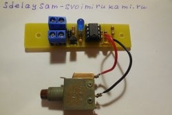
This key, built on powerful field-effect transistors, is designed to control the load by pressing a clock button: one press - turn on, press again - turn off.
This key is good because it does not interfere with the circuit. Thanks to the use of powerful mosfets, the resistance of the switch in the open state is thousandths of an ohm. At these values, even when driving a powerful load, no transistor heatsinks are required. When using bipolar transistors, such parameters cannot be achieved.
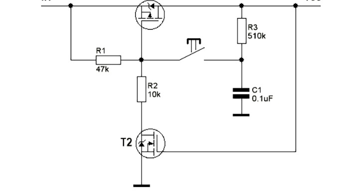
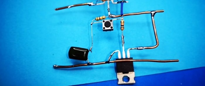
The first transistor switches the load, the second serves to hold the desired position.
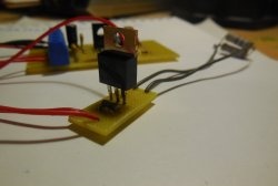
We tin and unbend the output of the IRFZ44N transistor.
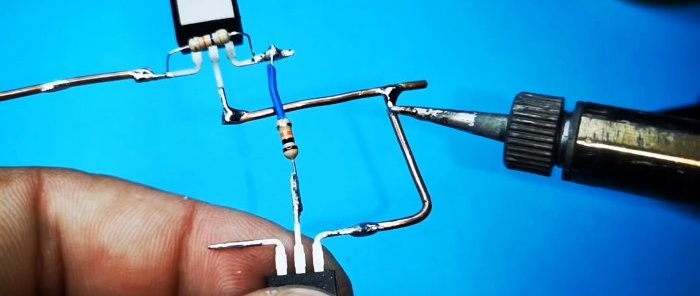
Solder a 47 kOhm resistor between the source and gate. We solder a 10 kOhm resistor to the gate.
We solder the IRF4905P transistor to the 10 kOhm resistor as a source. We solder the gate to the drain of the IRFZ44N.
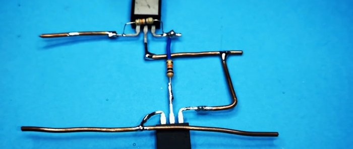
We solder the power buses from thick wire.
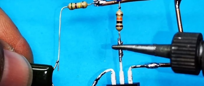
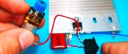
Solder the resistor and capacitor according to the diagram.
At the end there is a tact button without fixation.
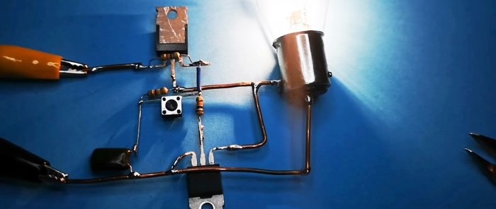
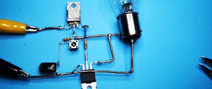
The scheme is ready. We use an incandescent lamp as a load. The device will be powered from 12 V.
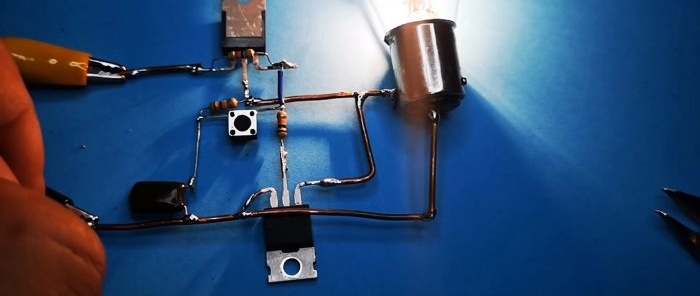
We press the button, the lamp lights up.
Press again - it goes out.
Maximum voltage: 60 V, maximum current: 50 A - according to the datasheet for the control transistor.
This key is good because it does not interfere with the circuit. Thanks to the use of powerful mosfets, the resistance of the switch in the open state is thousandths of an ohm. At these values, even when driving a powerful load, no transistor heatsinks are required. When using bipolar transistors, such parameters cannot be achieved.
Parts you will need
- Transistors IRFZ44N - 2 pieces -
- Transistors IRF4905P - 2 pieces -
- Resistors: 10 kOhm, 47 kOhm, 510 kOhm.
- Capacitor 0.1 µF.
- Tact button.
Scheme

The first transistor switches the load, the second serves to hold the desired position.
Making an electronic switch using MOSFET
We tin and unbend the output of the IRFZ44N transistor.
Solder a 47 kOhm resistor between the source and gate. We solder a 10 kOhm resistor to the gate.
We solder the IRF4905P transistor to the 10 kOhm resistor as a source. We solder the gate to the drain of the IRFZ44N.
We solder the power buses from thick wire.
Solder the resistor and capacitor according to the diagram.
At the end there is a tact button without fixation.
The scheme is ready. We use an incandescent lamp as a load. The device will be powered from 12 V.
We press the button, the lamp lights up.
Press again - it goes out.
Maximum voltage: 60 V, maximum current: 50 A - according to the datasheet for the control transistor.
Watch the video
Similar master classes
Particularly interesting
Comments (7)

