How to perform a full check of the rotor and stator with a multimeter using an angle grinder as an example
If the motor of a power tool burns out, then to repair it it is necessary to determine what is shorted - the rotor or the stator. This can be done with a multimeter. Checking with it is the most accessible method, since the average user simply does not have any other equipment.
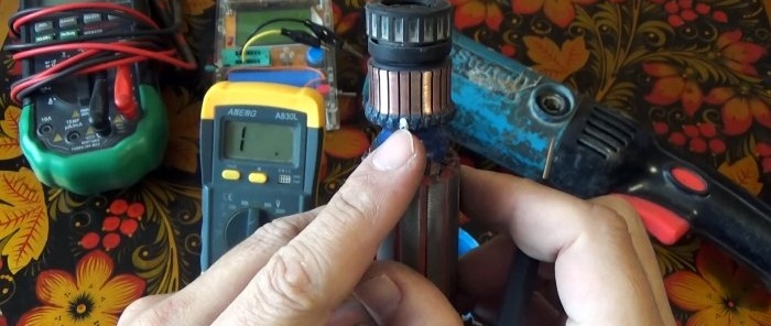
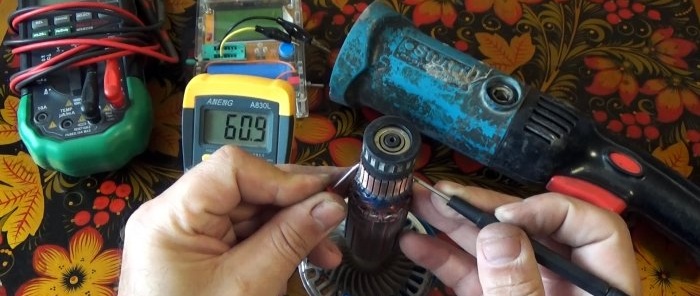
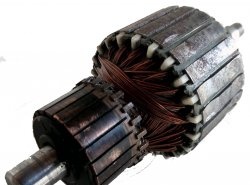
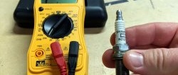
Multimeter need to be switched to 200 Ohm mode. One mark is placed on any armature commutator lamella and a second mark is placed opposite it.
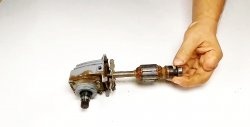
Then the tool probes are pressed against the marked contacts. It is necessary to take readings on the device display. Then the probes move to the contacts located to the right of the marks. Thus, you need to take readings by moving along the lamellas around the entire circumference. The resistance in each pair of opposite lamellas in a working armature is approximately the same.
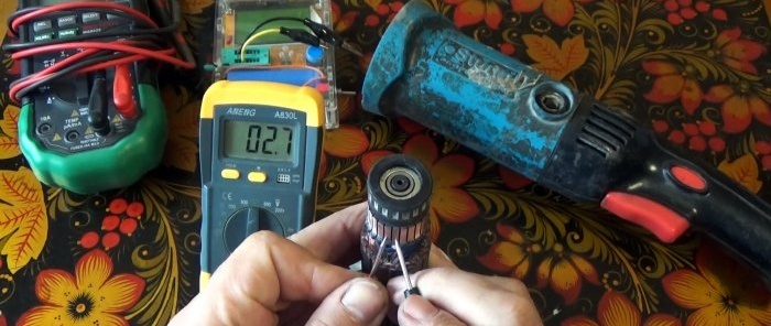
Multimeter also set to 200 ohms. Then the resistance between adjacent collector lamellas is measured with probes. Next you need to move to the right. That is, one probe goes to the next contact, and the rear one is installed instead. So you need to go through all the lamellas in a circle.A working rotor has approximately the same resistance in each pair.
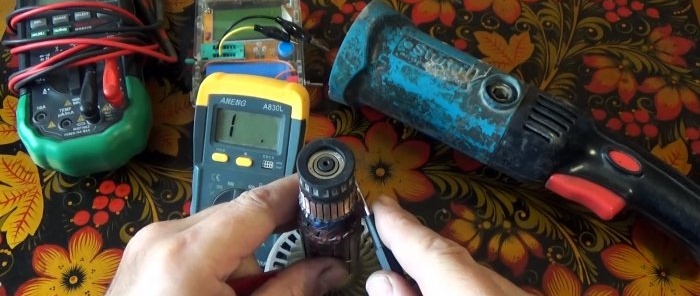
Multimeter is set to dial. Stripped copper wire can then be wound around the armature core to close all the ribs. After this, one probe is pressed against it, and the second one in turn against each individual lamella of the collector. If multimeter will give a sound signal, then the rotor is closed.
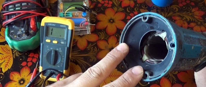
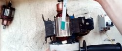
The stator is also checked with a multimeter in 200 Ohm mode. It is necessary to measure the resistance in its windings.
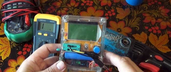
For a working stator it is the same. But a more effective test will be if you check the windings for inductance using the common Chinese tester ESR T4 -
Also see how you can make a device from a transformer to check the armature of an electric motor - https://home.washerhouse.com/en/7278-kak-iz-transformatora-sdelat-ustrojstvo-dlja-bystroj-proverki-jakorja-jelektrodvigatelja.html
Checking the anchor using the “180°” method
Multimeter need to be switched to 200 Ohm mode. One mark is placed on any armature commutator lamella and a second mark is placed opposite it.
Then the tool probes are pressed against the marked contacts. It is necessary to take readings on the device display. Then the probes move to the contacts located to the right of the marks. Thus, you need to take readings by moving along the lamellas around the entire circumference. The resistance in each pair of opposite lamellas in a working armature is approximately the same.
Checking the anchor on the lamellas in pairs
Multimeter also set to 200 ohms. Then the resistance between adjacent collector lamellas is measured with probes. Next you need to move to the right. That is, one probe goes to the next contact, and the rear one is installed instead. So you need to go through all the lamellas in a circle.A working rotor has approximately the same resistance in each pair.
Checking the anchor for continuity
Multimeter is set to dial. Stripped copper wire can then be wound around the armature core to close all the ribs. After this, one probe is pressed against it, and the second one in turn against each individual lamella of the collector. If multimeter will give a sound signal, then the rotor is closed.
Stator check
The stator is also checked with a multimeter in 200 Ohm mode. It is necessary to measure the resistance in its windings.
For a working stator it is the same. But a more effective test will be if you check the windings for inductance using the common Chinese tester ESR T4 -
Also see how you can make a device from a transformer to check the armature of an electric motor - https://home.washerhouse.com/en/7278-kak-iz-transformatora-sdelat-ustrojstvo-dlja-bystroj-proverki-jakorja-jelektrodvigatelja.html
Watch the video
Similar master classes
Particularly interesting
Comments (0)

