How to make a multimeter from PVC pipe for an auto electrician and a home craftsman
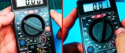
To repair battery tools, car wiring and similar tasks, you need multimeter direct current. This device can be made with your own hands from inexpensive components from the radio market. This device will be able to measure voltage, do dialectics and other diagnostics.
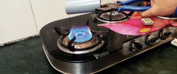
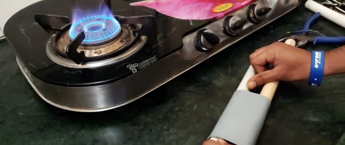
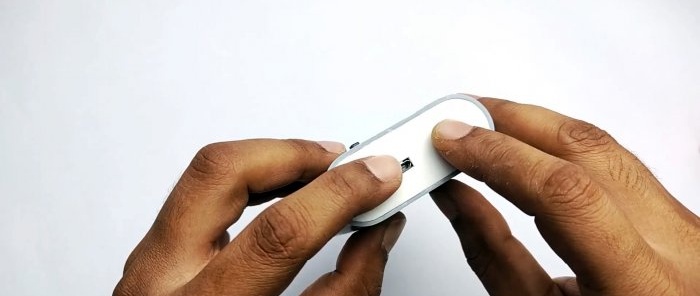
A piece of plastic pipe with a diameter of 50 mm needs to be heated and then flattened, stretched with two 20 mm tubes. The result should be a body multimeter.
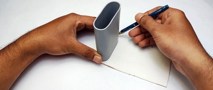
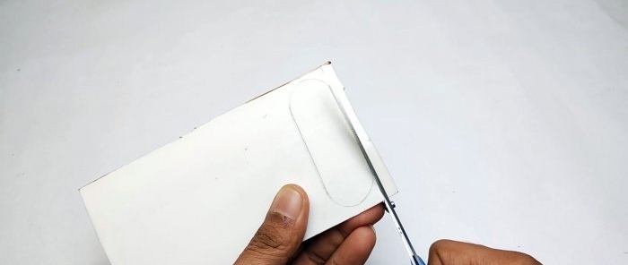
The edges of the body are polished. Plugs for it are cut out of sheet plastic. You can just line up another piece of pipe and make them from that.
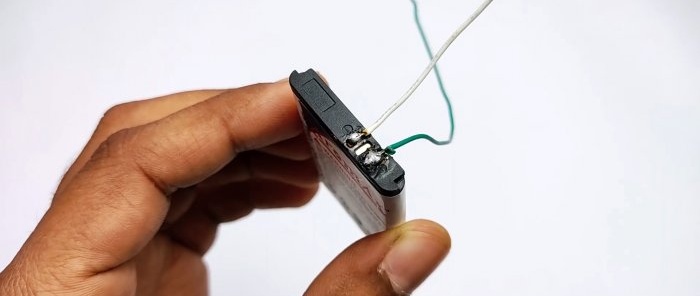
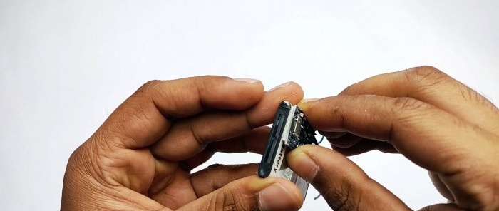
Short wires are soldered to the side contacts of the battery.
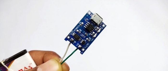
Then they are soldered to the charging module according to the proposed circuit.
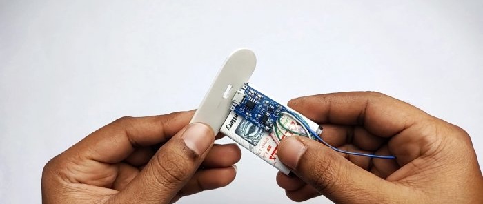
2 output wires are soldered to the module contacts, and it is glued to the battery.
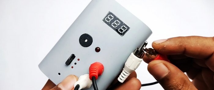
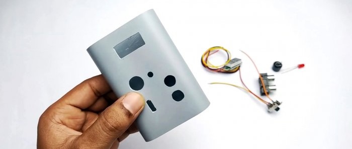
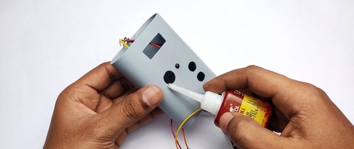
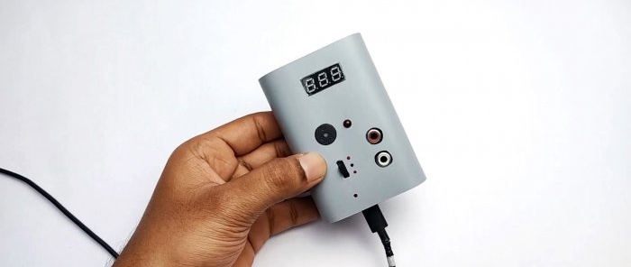
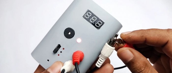
The windows required for installing the buzzer are cut on the front side of the case, LED, voltmeter, switch, as well as 2 tulip sockets.
A hole is cut on one plug for the Micro USB cable.
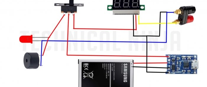
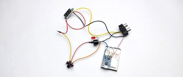
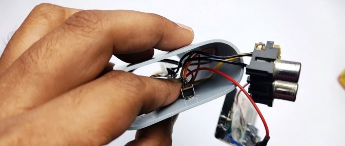
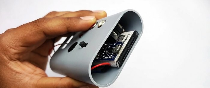
After this, the components are connected according to the diagram and placed in the housing, where they are fixed with glue.
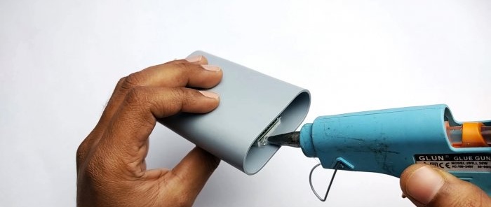
Before gluing in the plugs, you will need to make a hole opposite the charging module indicator light.
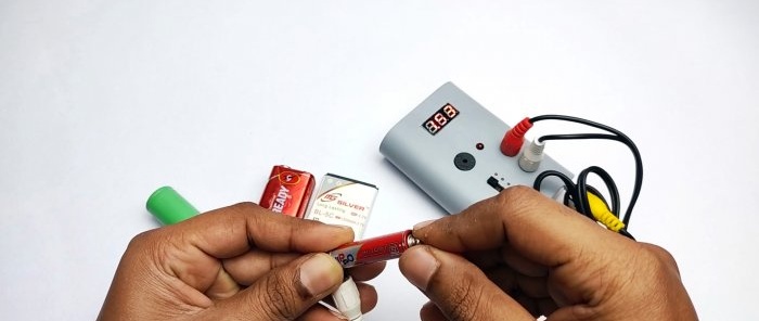
As a result, we get a battery voltmeter with RCA cable probes. They can check the voltage in DC networks, as well as make a continuity test with sound and light indication.
Materials:
- sewer pipe 50 mm;
- sheet plastic;
- digital voltmeter -
- battery from a push-button mobile phone 3.7V -
- Micro USB charging module for Li-ion batteries TP4056 -
- SPDT slide switch;
- buzzer 5V -
- red Light-emitting diode -
- RCA socket for 2-3 contacts;
- RCA cord with 2 pairs of plugs.
Manufacturing process of a simple multimeter
A piece of plastic pipe with a diameter of 50 mm needs to be heated and then flattened, stretched with two 20 mm tubes. The result should be a body multimeter.
The edges of the body are polished. Plugs for it are cut out of sheet plastic. You can just line up another piece of pipe and make them from that.
Short wires are soldered to the side contacts of the battery.
Then they are soldered to the charging module according to the proposed circuit.
2 output wires are soldered to the module contacts, and it is glued to the battery.
The windows required for installing the buzzer are cut on the front side of the case, LED, voltmeter, switch, as well as 2 tulip sockets.
A hole is cut on one plug for the Micro USB cable.
After this, the components are connected according to the diagram and placed in the housing, where they are fixed with glue.
Before gluing in the plugs, you will need to make a hole opposite the charging module indicator light.
As a result, we get a battery voltmeter with RCA cable probes. They can check the voltage in DC networks, as well as make a continuity test with sound and light indication.
Watch the video
Similar master classes
Particularly interesting
Comments (2)

