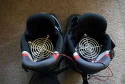
Shoe dryer
To effectively dry shoes, a constant flow of warmer, and therefore less humid air than the surrounding air is necessary. The proposed dryer works on this principle, the diagram of which is shown in Fig. 1. Resistors R1—R12 are used as heating elements. The fan blows them, and the heated air flows through the air ducts into the shoes.
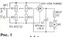
The supply voltage to the DC electric motor M1 of the fan is supplied through the rectifier bridge VD1-VD4, thanks to which the device can be powered from a source of both direct and alternating current (in the latter case, capacitor C1 smoothes out the ripples of the rectified voltage).
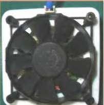
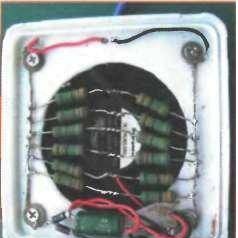
Structurally, the dryer consists of a heating chamber and two air pipes inserted into the shoes. The heating chamber is made of a plastic junction box with dimensions of 100x100x35 mm, intended for electrical wiring. A hole with a diameter of 70 mm is cut out in its cover and a fan from the power supply of a personal computer (Fig. 2) and a two-pin instrument plug for connecting the power source are fixed on the outside. The fan is installed so that it forces air inside the box.On the back side of the cover (Fig. 3) the remaining elements are mounted: resistors R1-R12 - above the hole for the fan (so that they can be blown with air), and diodes VD1-VD4, capacitor C1 and resistor R13 - next to the wall of the cover (after checking the device for It is advisable to secure them with hot-melt adhesive to ensure their functionality).
Holes for air duct pipes are cut in the side wall of the housing. It is convenient to use plastic (non-reinforced) water pipes with an internal diameter of 3/4 inch (19 mm). They can be easily processed with simple tools, and when heated, they can be deformed (bent). Cut two pieces to the required length. At one end of each of them, a sharp knife is used to make a cut to approximately half the diameter and, at a distance of approximately 60 mm from one another, two holes are drilled for the mounting screws.
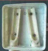
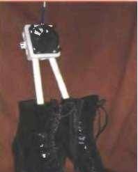
Then, having drilled the same holes in the bottom of the box, the air duct pipes are attached to it with screws and MZ nuts (Fig. 4). Their opposite ends, after heating over a gas (or electric) stove, can be bent at the desired angle. For better and uniform air outlet, it is advisable to drill several holes with a diameter of 4...5 mm in the pipe walls. The appearance of the dryer in working position is shown in Fig. 5.
In the dryer, you can use resistors C2-23, MLT with a dissipated power of 2 W and an oxide capacitor K50-35 or a similar imported one; diodes - any small-sized rectifier with a forward current of at least 200 mA and a reverse voltage of at least 50 V (it is possible to use a ready-made rectifier unit, for example KTs407A). The power source, as mentioned, is DC or AC with an output voltage of 12... 14 V with a load current of at least 3.5 A.Suitable, for example, is a power supply from a personal computer or a step-down (220/12 V) transformer for halogen lamps. The fan rotation speed is regulated by selecting resistor R13 (it should not be set to the maximum possible, as this will lead to a decrease in the temperature of the supplied air).

A further development of the device could be the automation of the drying process, for example, the introduction of a thermal control system or a timer that turns off the dryer after a specified time.
Similar master classes
Particularly interesting
Cable antenna for digital TV in 5 minutes
A selection of simple and effective schemes.
Three-phase voltage from single-phase in 5 minutes
Starting a three-phase motor from a single-phase network without a capacitor
Eternal flashlight without batteries
How to make an inexpensive but very powerful LED lamp
Comments (2)

