Refinement of the charger - adding heat sinks
Hello dear readers! This is my first article, so don't judge too harshly. Today we will talk about improving the Chinese battery charger, namely “liitokala lii-500 engineer”.
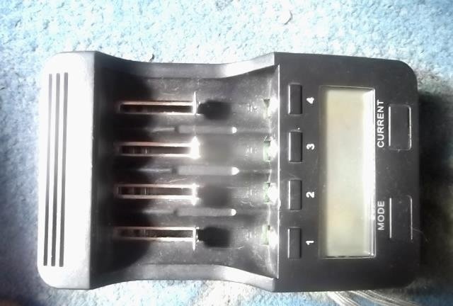
The background is what prompted me to finalize it. I once bought myself such a charger, and I liked it, but the problem was that it died after a year, I used it without turning it off, and it measured the capacity for this year to be approximately 2000 cans of 18650 li-ion. Afterwards I tried to fix it, but it didn’t work for more than a week. Accordingly, I spat on it and bought a new one of the same kind, and unsoldered the old one into a box. And in this article, I decided to complete it with a new charger, so that it would not break for a long time.
Let's begin!
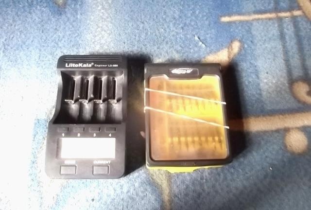
First of all, we unscrew the case, there are 6 screws on the litocal and they are on the bottom.
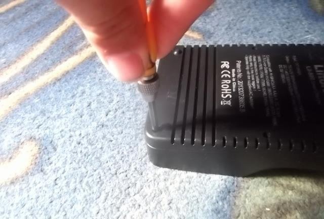
Remove the cover from this device.
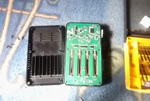
And what do we see?
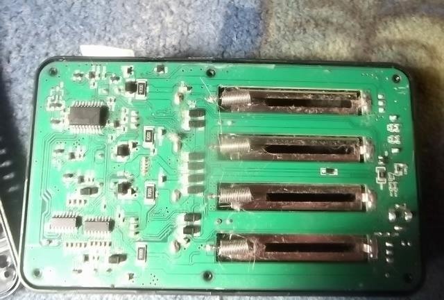
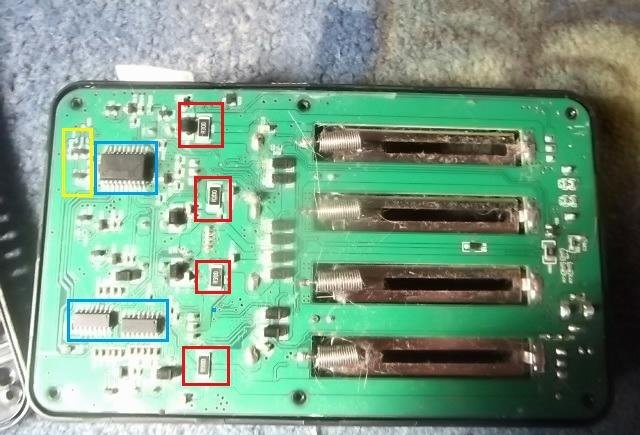
I marked in red the resistors that consume battery power when discharged, in blue the logic, the processor and two more small microcircuits, I still didn’t understand what kind of microcircuits they were, in yellow I marked the processor’s power circuit.
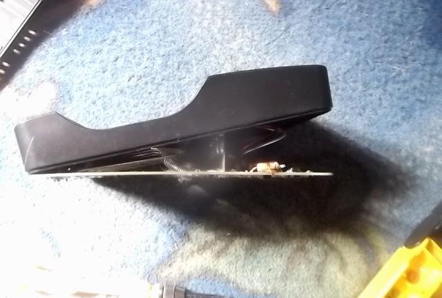
Let's continue the disassembly. We take out the board.
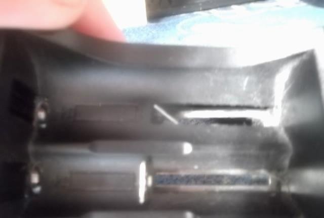
The board rests against the contacts, so we pull them out. Turn the contacts sideways as shown in the photo. Be careful, do not bend the fastener with the letter G under any circumstances on the contact - since I already broke 1 on the old litocal which was the first.
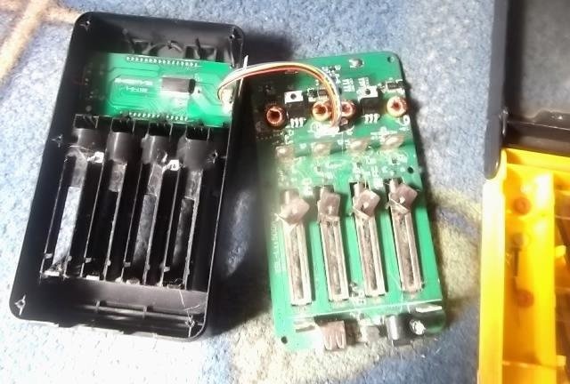
Hurray, we pulled it out!
Now you need to disconnect the connector from the screen.
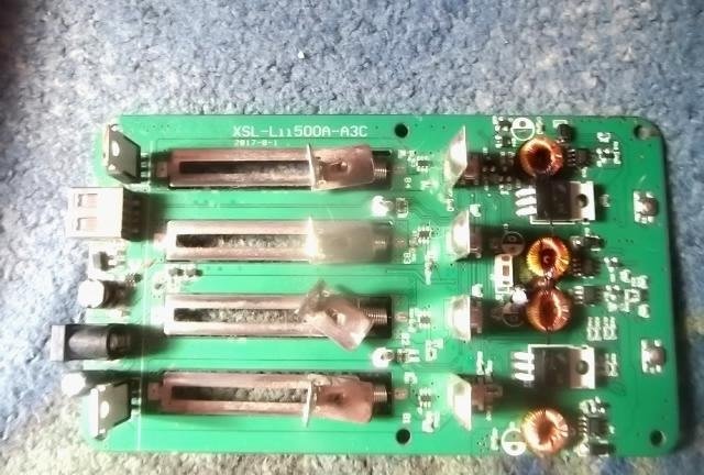
So we see:
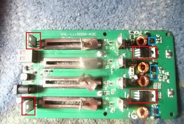
The red ones are the mofettes responsible for the discharge and the blue ones are responsible for the charge.
Also, on my copy of the charger, I noticed a very crookedly soldered diode, and this is how it was from the factory.
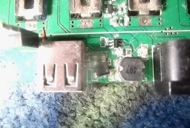
Let's move on to the finalization itself!
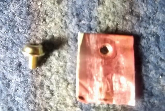
First of all, we cut small radiators; you can also supply ready-made radiators, but I don’t have them, so I made them from a piece of copper busbar of the ATX power supply transformer.
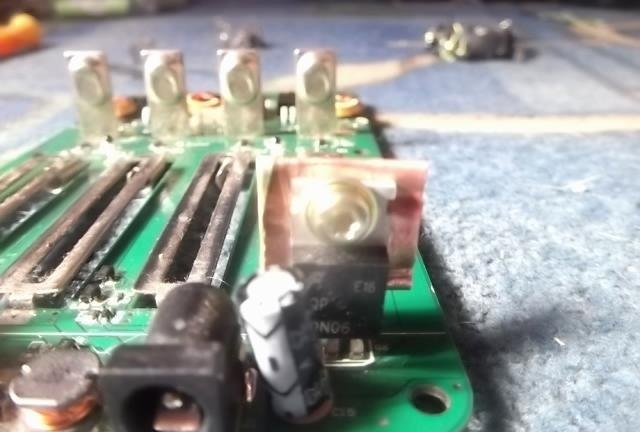
We screw them on.
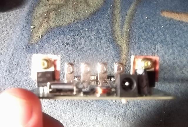
We do the same with the second one.
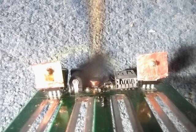
This is what it looks like for me.
The camera can't get focus. We take a copper plate, cut it out as in the photo and glue it with second glue.
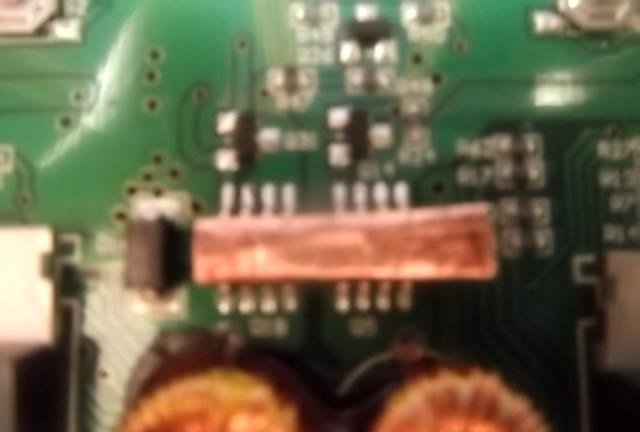
Charge transistors in the middle.
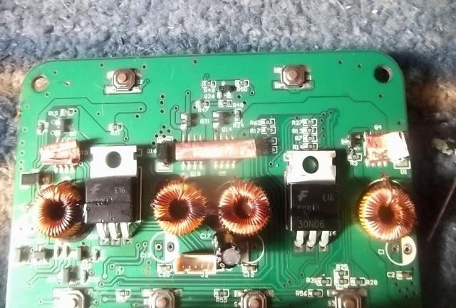
We also cut out and glue onto the side charge transistors of slots 1 and 4
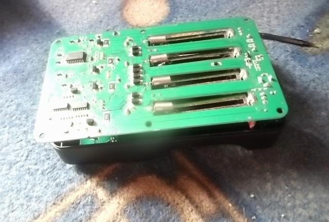
After the glue of the radiators has dried, we begin to assemble.
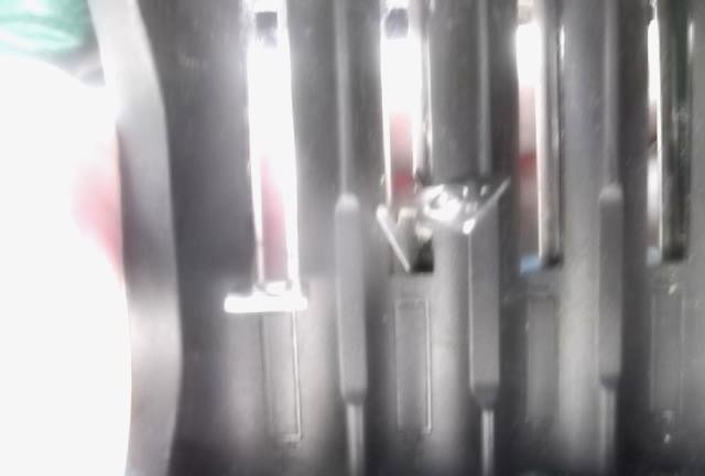
We put the contacts sideways in place and this is much more difficult than removing them.
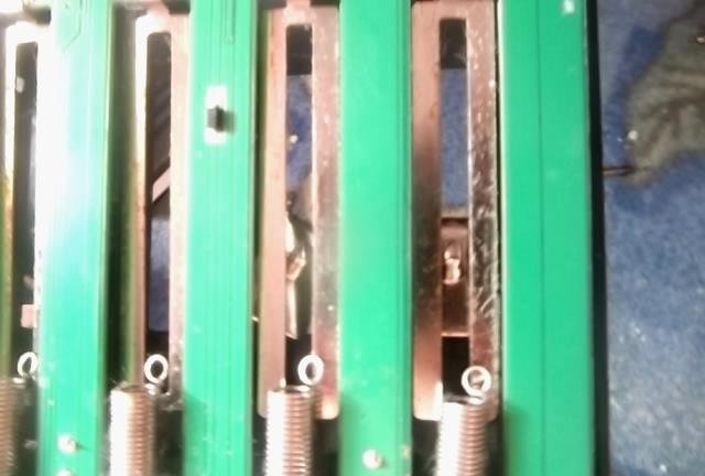
We cling to the springs.
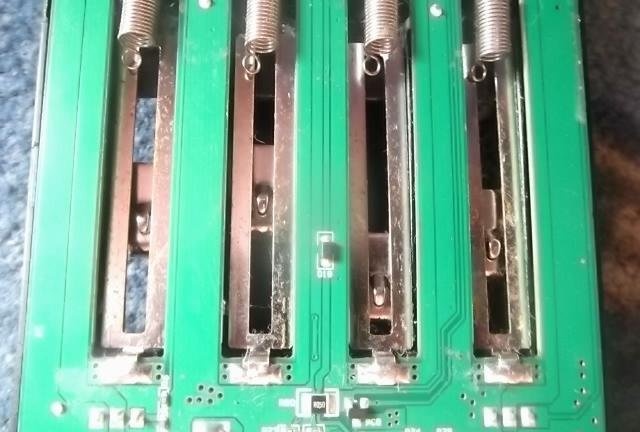
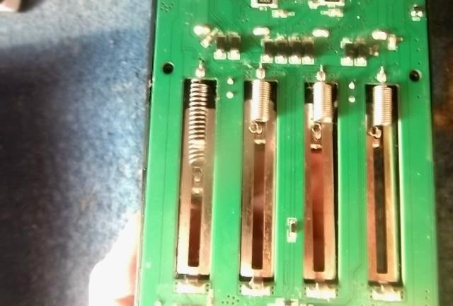
To do this, we hook the spring with our fingernail and pull it down; it won’t work on the first try, but it will work on the 6th or 7th try.
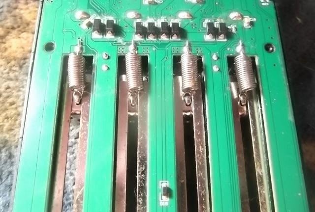
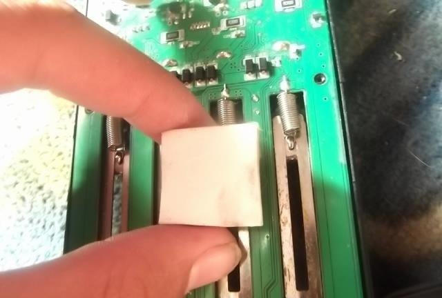
Now let's take some thermal gum.
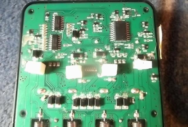
The mode is divided into pieces and first of all we put it on the resistors, since they get very hot.
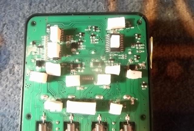
We put the rest as here. But this is optional since everything else heats up less.
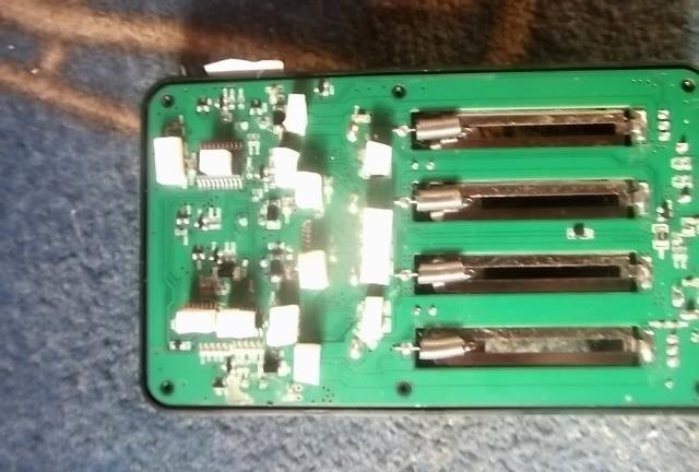
Now let's assemble this device.
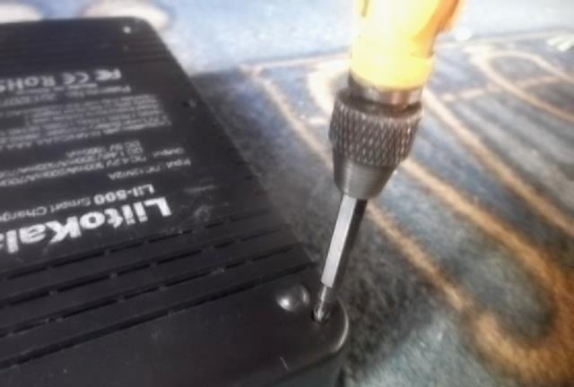
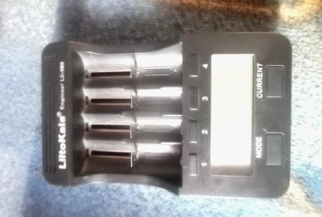
Ready!
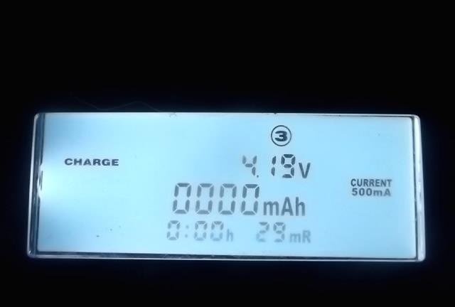
Now let's check for functionality. Everything worked for me on the first try.

The background is what prompted me to finalize it. I once bought myself such a charger, and I liked it, but the problem was that it died after a year, I used it without turning it off, and it measured the capacity for this year to be approximately 2000 cans of 18650 li-ion. Afterwards I tried to fix it, but it didn’t work for more than a week. Accordingly, I spat on it and bought a new one of the same kind, and unsoldered the old one into a box. And in this article, I decided to complete it with a new charger, so that it would not break for a long time.
We are finalizing the charger
Let's begin!

First of all, we unscrew the case, there are 6 screws on the litocal and they are on the bottom.

Remove the cover from this device.

And what do we see?


I marked in red the resistors that consume battery power when discharged, in blue the logic, the processor and two more small microcircuits, I still didn’t understand what kind of microcircuits they were, in yellow I marked the processor’s power circuit.

Let's continue the disassembly. We take out the board.

The board rests against the contacts, so we pull them out. Turn the contacts sideways as shown in the photo. Be careful, do not bend the fastener with the letter G under any circumstances on the contact - since I already broke 1 on the old litocal which was the first.

Hurray, we pulled it out!
Now you need to disconnect the connector from the screen.

So we see:

The red ones are the mofettes responsible for the discharge and the blue ones are responsible for the charge.
Also, on my copy of the charger, I noticed a very crookedly soldered diode, and this is how it was from the factory.

Let's move on to the finalization itself!

First of all, we cut small radiators; you can also supply ready-made radiators, but I don’t have them, so I made them from a piece of copper busbar of the ATX power supply transformer.

We screw them on.

We do the same with the second one.

This is what it looks like for me.

The camera can't get focus. We take a copper plate, cut it out as in the photo and glue it with second glue.

Charge transistors in the middle.

We also cut out and glue onto the side charge transistors of slots 1 and 4

After the glue of the radiators has dried, we begin to assemble.

We put the contacts sideways in place and this is much more difficult than removing them.

We cling to the springs.


To do this, we hook the spring with our fingernail and pull it down; it won’t work on the first try, but it will work on the 6th or 7th try.


Now let's take some thermal gum.

The mode is divided into pieces and first of all we put it on the resistors, since they get very hot.

We put the rest as here. But this is optional since everything else heats up less.

Now let's assemble this device.


Ready!

Now let's check for functionality. Everything worked for me on the first try.
Similar master classes
Particularly interesting
Comments (8)

