Air compressor from a ZIL unit and a washing machine engine
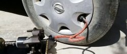
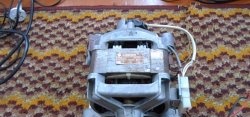
Owners of cars, motorcycles and cyclists often have to inflate their wheels; doing this manually is long and tedious. An air compressor comes to the rescue, which can be assembled from a working automobile unit. A 300-watt motor is excellent as a drive for it - these are often used to equip rotary and automatic washing machines. Let us consider in detail the process of creating the mentioned device.
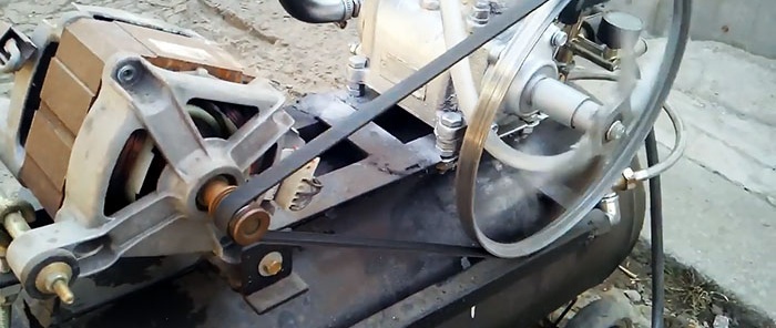
The process of manufacturing an air compressor requires metalworking and plumbing skills from a craftsman. For the work, a number of components and parts were needed: new or used:
To perform the work you will need a mechanic's tool, a drill with a set of drills and electric welding. Some operations, for example, boring a pulley, are ordered in a specialized workshop.
Most of the components were used; they were cleaned of contaminants and, if necessary, rebuilt. The main parts of the compressor were made in the garage and assembled in the following sequence:
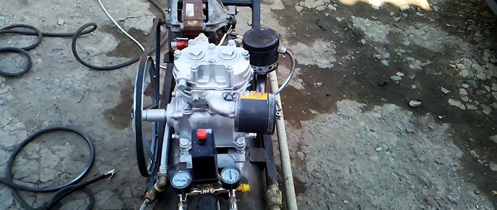
The automobile unit is mounted on the receiver frame using bolted connections.
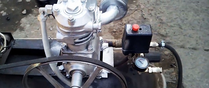
An electric drive is installed next to it so that the pulleys are in the same plane.
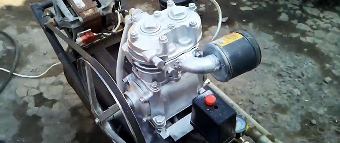
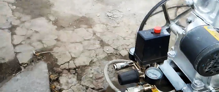
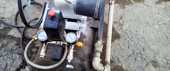
In front of the compressor on the frame, we mount the automatic control system and reconfigure it: switching on at a pressure of 4 atm, switching off at 6 atm.
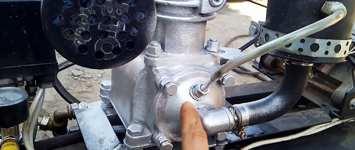
We drill a hole in the compressor crankcase cover, cut a thread and screw in a square. We attach a tube with an oil tank to it, and above we cut in a breather through which the oil will be squeezed into the storage tank.
We weld an air cooling radiator from steel tubes, which simultaneously functions as a handle for transportation. On one side we connect the outlet from the compressor to it; on the other, we connect the air supply tube to the receiver.
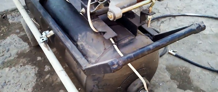
We turn the air line using two squares.
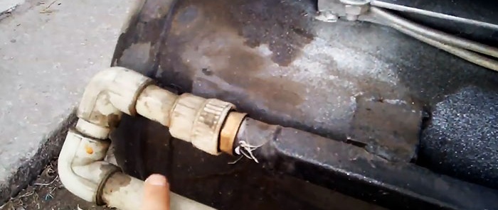
We install a check valve at the inlet of the receiver.
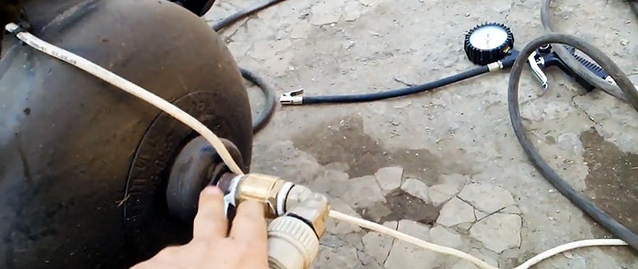
At the outlet of the receiver, install a valve and connect a flexible hose reinforced with thread.
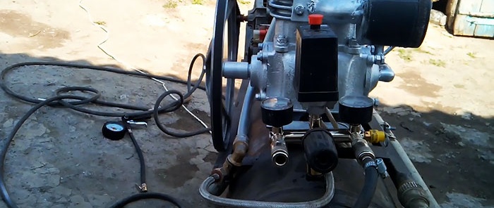
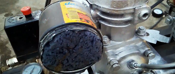
We install an air filter made from a plastic jar with a lid with holes drilled in it onto the suction pipe of the compressor.
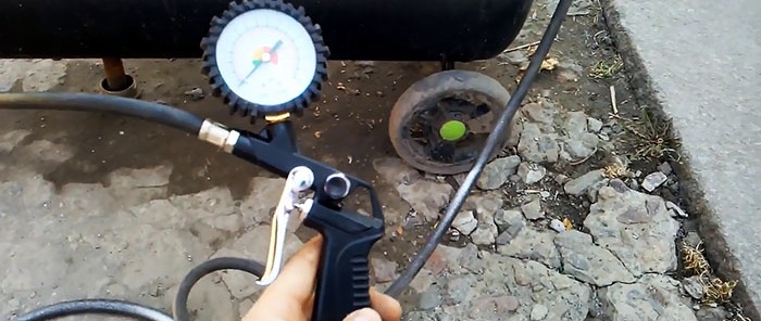
At the other end of the hose we mount a tire inflation gun.
A foam sponge cut to size is used as a filter element.
The ratio of the drive and driven pulleys is 1 to 13, which allows the 13,000 rpm of the electric motor to be reduced to 1,000 rpm on the compressor.

This ensures normal operation of the unit and rapid build-up of pressure in the receiver. Automatic upon reaching 6 atm. turns off the power supply to the drive, and as air consumption increases, the cycle repeats.

Materials, components and tools used
The process of manufacturing an air compressor requires metalworking and plumbing skills from a craftsman. For the work, a number of components and parts were needed: new or used:
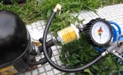
- Compressor for truck ZIL-130 or ZIL-131.
- Electric motor with a rated power of 300 W, single-phase, voltage 220 V.
- Large and small pulleys.
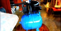
- Receiver: steel cylinder.
- Automatic control systems made in China with manometers.
- Plumbing fittings: collet tees, elbows and check valve.
- Profile steel, metal-plastic and plastic pipes.
To perform the work you will need a mechanic's tool, a drill with a set of drills and electric welding. Some operations, for example, boring a pulley, are ordered in a specialized workshop.
The procedure for manufacturing and assembling the compressor
Most of the components were used; they were cleaned of contaminants and, if necessary, rebuilt. The main parts of the compressor were made in the garage and assembled in the following sequence:
The automobile unit is mounted on the receiver frame using bolted connections.

An electric drive is installed next to it so that the pulleys are in the same plane.

In front of the compressor on the frame, we mount the automatic control system and reconfigure it: switching on at a pressure of 4 atm, switching off at 6 atm.

We drill a hole in the compressor crankcase cover, cut a thread and screw in a square. We attach a tube with an oil tank to it, and above we cut in a breather through which the oil will be squeezed into the storage tank.

We weld an air cooling radiator from steel tubes, which simultaneously functions as a handle for transportation. On one side we connect the outlet from the compressor to it; on the other, we connect the air supply tube to the receiver.

We turn the air line using two squares.

We install a check valve at the inlet of the receiver.

At the outlet of the receiver, install a valve and connect a flexible hose reinforced with thread.

We install an air filter made from a plastic jar with a lid with holes drilled in it onto the suction pipe of the compressor.

At the other end of the hose we mount a tire inflation gun.

A foam sponge cut to size is used as a filter element.

The ratio of the drive and driven pulleys is 1 to 13, which allows the 13,000 rpm of the electric motor to be reduced to 1,000 rpm on the compressor.

This ensures normal operation of the unit and rapid build-up of pressure in the receiver. Automatic upon reaching 6 atm. turns off the power supply to the drive, and as air consumption increases, the cycle repeats.

Watch the video
Similar master classes
Particularly interesting
Comments (1)

