Discharge indicator for any battery
This circuit is characterized by a clear switching threshold when the set voltage level is reached. This indicator is universal, has a potentiometer for setting a given value and can work with any battery in the range of 3-16 V.
Will need
- Two PN2222 transistors, NPN structures.
- Light-emitting diode 3 V.
- Variable resistor 10 kOhm.
- Two 4.7 kOhm resistors.
- One resistor each 56 kOhm and 460 Ohm.
There are no special requirements for parts; everything can be replaced with similar ones without any problems. In terms of resistors, the deviation from the nominal value can be 10 percent. It's not scary, take those close in meaning.
Manufacturing of a universal discharge indicator
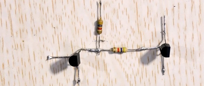
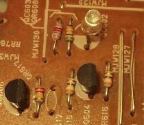
We take the transistors and unbend the terminals.
We solder a 4.7 kOhm resistor to one to its base.
Next, we take the second one and solder it to the same resistor with the collector.
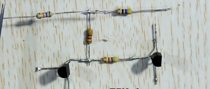
Now we solder another 4.7 kOhm resistor.
Next we solder at 56 kOhm on the left and 460 Ohm on the right.
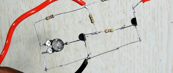
Solder the potentiometer.
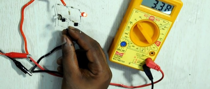
It's getting to work Light-emitting diode.
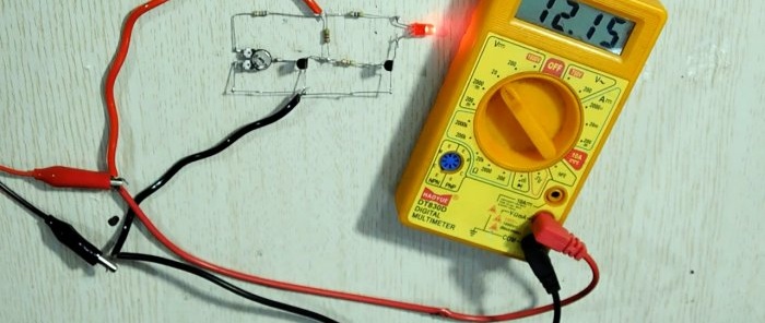
Complete diagram with all symbols.
How does the scheme work?
The potentiometer sets the response level, this has already been decided. The transistor on the left contains a threshold element, the transistor on the right contains a key for LED.
For example, let's set the response level to 3.5 V. If the voltage on the circuit is higher, say 3.6 V, then the first transistor is open and the key is locked. Light-emitting diode in this case it does not light up. The indicator consumes minimal current.
If the voltage drops below the threshold value and is, say, 3.48 V, then the first transistor closes and the key opens. As a result, we see a glow LED, indicating conditionally that the battery is discharged.
The circuit also works perfectly in the 12 V range.
This makes it possible to use the indicator for any batteries or batteries in the range of 3-12 V.
Watch the video
Similar master classes
Particularly interesting
Comments (3)

