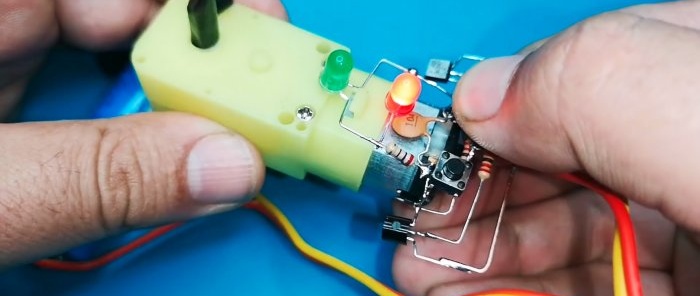
Scheme of reversible control of an electric motor with two clock buttons
The device is designed to control an electric motor for children's toys, powered by a AA battery. It turns it on by selecting the direction of rotation of the rotor. The functions of the control elements are performed by pressing buttons, and LED indication is also provided.
Main advantages of the scheme
- The first and main advantage: there is no need to use a bulky switch with several contact groups for reverse;
- non-deficient components are used during assembly;
- no selection of transistors according to parameters is required;
- It is possible to use even transistors of different types, provided that their maximum power dissipation is close and their structure matches.
Circuit features of the device
The circuit diagram is shown in the figure and actually consists of two identical transistor switches.
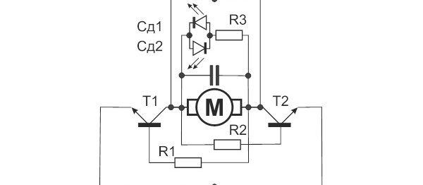
The transistors operate in switch mode and are connected in series with the load, which is a low-power DC electric motor M.When you press the Cl1 button, the plus of the power source is supplied to one of the terminals of the electric motor and, through resistor R1, to the base of transistor T1. The latter opens, current flows through the electric motor M and its rotor begins to rotate. At the same time it starts to glow Light-emitting diode CD1, the current through which is limited by resistor R3.
When the Cl2 button is closed, the second arm and the indicator assigned to it work in exactly the same way. Light-emitting diode. The difference is that the current through the electric motor M flows in the opposite direction. Accordingly, its rotor rotates in the other direction.
The maximum current through transistors T1, T2 is limited by the resistance of the electric motor M. Capacitor C functions as an overvoltage protection element at the time of switching.
Element base
The device is assembled using the following components:- two BC547 transistors (pinout is presented below) - http://alii.pub/5l6vyg
- capacitor with a nominal value of 100 nF - http://alii.pub/5n14g8
- three resistors with a resistance of 220 Ohms - http://alii.pub/5h6ouv
- two red and green LEDs with an operating current of up to 50 mA - http://alii.pub/5lag4f
- two buttons for closing without fixing - http://alii.pub/5nnu8o
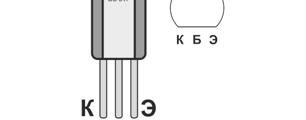
Installation and commissioning
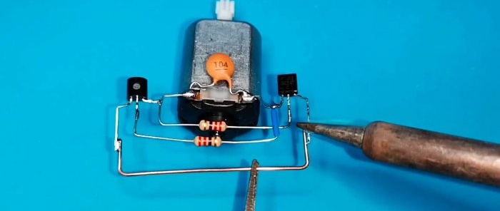
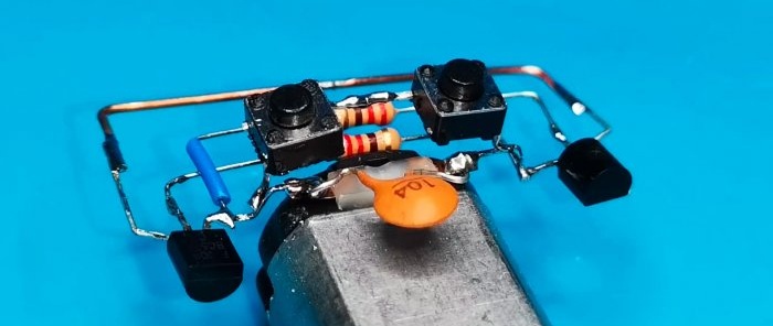
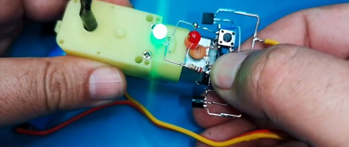
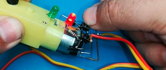
Due to the small number of components, installation can be carried out in weight with soldering the leads of radio components to each other and using an electric motor as a supporting platform. The terminals of the elements at the intersections with each other should be protected with cambrics.
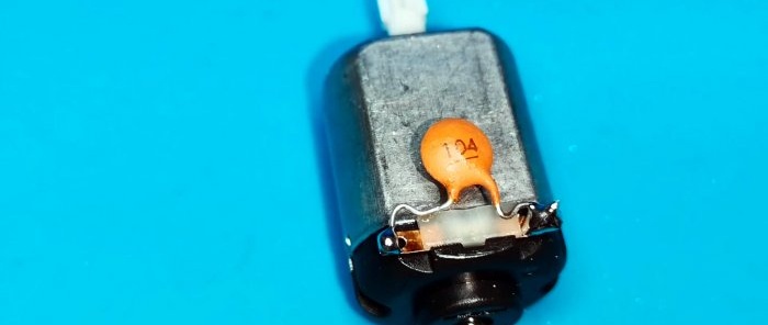
We first solder the capacitor to the motor poles.
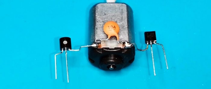
We form the output of the transistors and solder them according to the diagram.
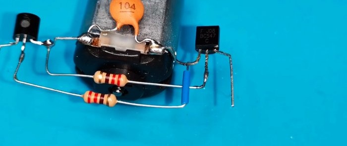
Solder the resistors. The output of one is insulated with a cambric.
We will make the bus from a piece of copper wire.
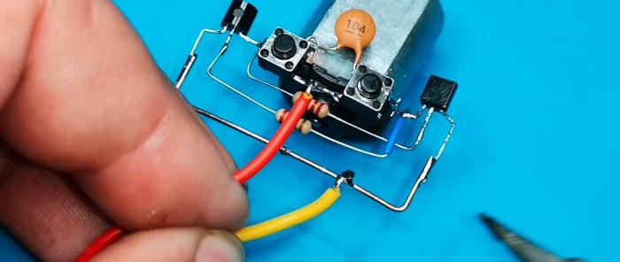
We connect the buttons in series and solder them.
We connect the power wires.
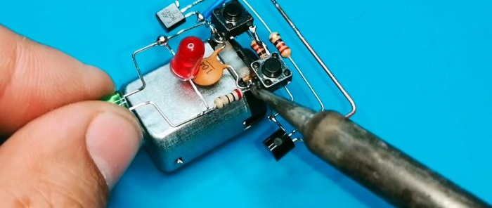
Connecting LEDs in parallel and connect to the seme through a resistor.
The device does not require adjustment and, if assembled correctly, begins to function immediately after connecting the power and pressing one of the control buttons.

