Control devices from a PC desktop or via the Internet


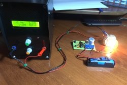
Light control via the Internet.

Naturally, you can control not only the light, but also any other device from your computer or remotely via the Internet. One device or several.

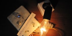
In the example we will control a lamp.
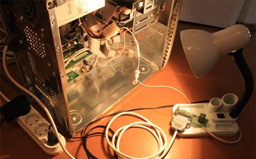

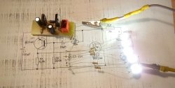
Manufacturing details in the picture.

So, the unit consists of hardware And software parts.

Part 1. Hardware

We will need the following parts:

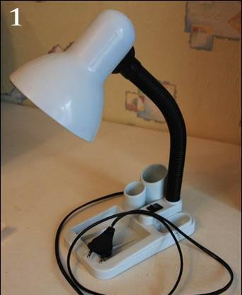
1. Lamp 220 V;

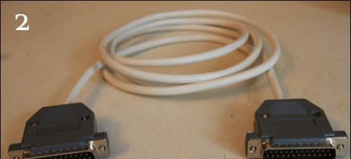
2. lpt extension;


3. Fee;
4. angled LPT connector to the board;
5. relay 12 VDC and switching voltage 220 volts;
6. 4.7K resistor;
7. NPN transistor type KT3117A or any other with normal coefficient. amplification;
8. diode;
9. power splitter in the PC, if powered from the PC. But it is also possible from another 12 V source.


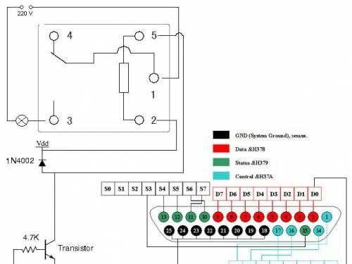
The device diagram is easy to assemble:


The gray rectangle on top is the relay.
If we apply one to pin D, voltage will appear on it and eventually the relay will switch, turning on the lamp.

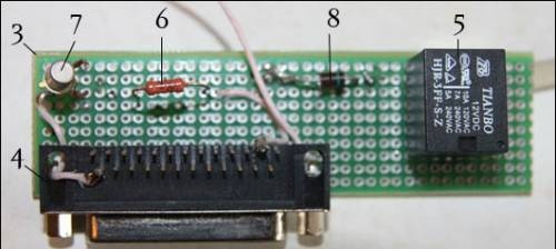
According to the above diagram we solder something like this:


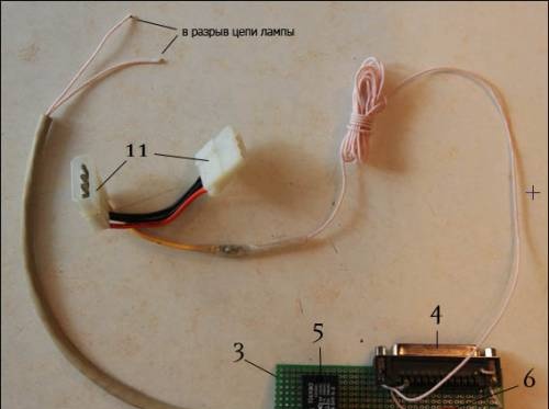
We solder the board into the open circuit of our lamp; connect via an lpt extension cable to the corresponding PC port; connect to the PC power supply via power splitter 11; Well, and the 220 V lamp itself.

Part two. Software

To revive our lamp, let's write a program in Delphi (the first thing that comes to hand is not at all difficult to rewrite in C, the program literally has 3 lines of code)

Source: /svetom/lamp_1.0.rar (this program can only turn the lamp on and off by pressing a key).
You can turn on a lamp or any other lamp from your computer!


Having slightly modernized the program, we get the second source: /svetom/lamp_2.0.rar (this program monitors a file that can be modified by the php script lamp2.php on the local web server).


Now we can turn on our favorite lamp from anywhere on the planet where there is Internet.


Good luck !

come back
Comment
  • bowtiesmilelaughingblushsmileyrelaxed relaxedsmirk
    heart_eyeskissing_heartkissing_closed_eyesflushedrelievedsatisfiedgrin
    winkstuck_out_tongue_winking_eyestuck_out_tongue_closed_eyesgrinningkissingstuck_out_tonguesleeping
    worriedfrowninganguishedopen_mouthgrimacingconfusedhushed
    expressionlessunamusedsweat_smilesweatdisappointed_relievedwearypassive
    disappointedconfoundedfearfulcold_sweatperseverecrysob
    joyastonishedscreamtired_faceangryragetriumph
    sleepyyummasksunglassesdizzy_faceimpsmiling_imp
    neutral_faceno_mouthinnocent
3+three=
Comments (19)
  1. phantom-111
    #1 phantom-111 Guests 21 January 2011 13:41
    1
    great idea! smile
  2. BAGZ
    #2 BAGZ Guests 21 May 2011 15:34
    0
    Can this be done via USB?
  3. NOTFRONT
    #3 NOTFRONT Guests 21 May 2011 18:05
    0
    Of course, take a USB to LPT adapter
  4. Co6epu_YA3uk
    #4 Co6epu_YA3uk Guests 27 July 2011 21:42
    0
    And if you use a 28v relay, will you have to replace the diode?
  5. Veent
    #5 Veent Guests 28 July 2011 22:53
    0
    The diode is for protection, you can solder it a little more powerfully. Where do you find 24 volts on your computer? It will be less of a mark if you find a 12 volt relay. But if not, then you need a more powerful transistor, an external power supply for 24 V + to Vdd - to the emitter of the transistor (without disconnecting it from GND)
  6. self-taught
    #6 self-taught Guests 18 June 2012 22:36
    1
    There are switches in irons, curling irons, photo switch sensors
  7. ruslan170777
    #7 ruslan170777 Guests July 1, 2012 11:03
    0
    who cares, draw a diagram for 2 3 4 devices
    1. Dmitriy
      #8 Dmitriy Guests 8 May 2018 18:33
      1
      For each channel - the same scheme.
  8. Artyom 111
    #9 Artyom 111 Guests 14 January 2013 14:46
    0
    Can this be done via USB?
  9. 1
    #10 1 Guests December 17, 2013 07:56
    0
    On the diagram indicate where to connect 12V.
  10. Sanya
    #11 Sanya Guests 5 January 2014 17:44
    0
    Connect +12 volts to the Vdd point (2 relays between the diode and the leg)!