We connect a low-voltage soldering iron to a 220 network without a transformer
I have been using low voltage soldering irons for a very long time. It just so happened that I got a few of them. They are powered by a safe 42 volts. Usually they are connected to a transformer, but I don’t have one. I use a quenching capacitor for power. About the calculation of the capacitor - further.
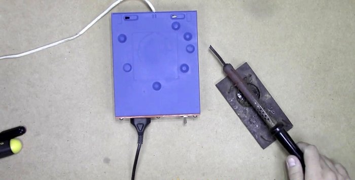
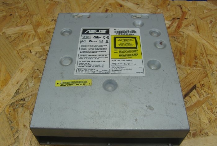
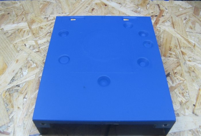
The case for the power supply of the soldering iron will be the case from an old DVD drive. I'm thinking of painting it, apparently I'll have to leave the sticker, with a guide for the disk underneath it. Removing it creates a hole, which I don’t need.
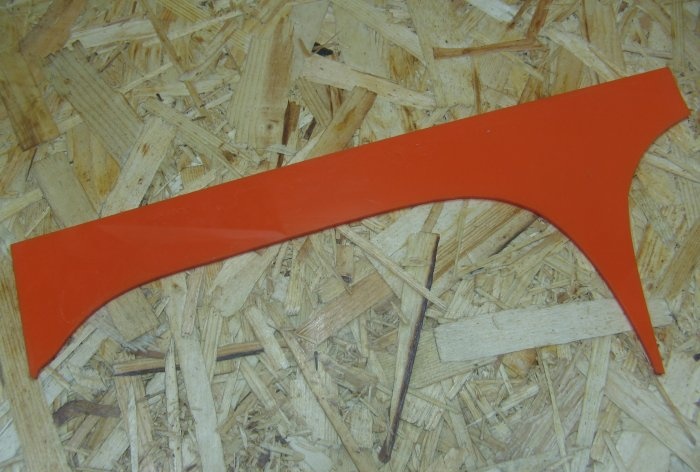
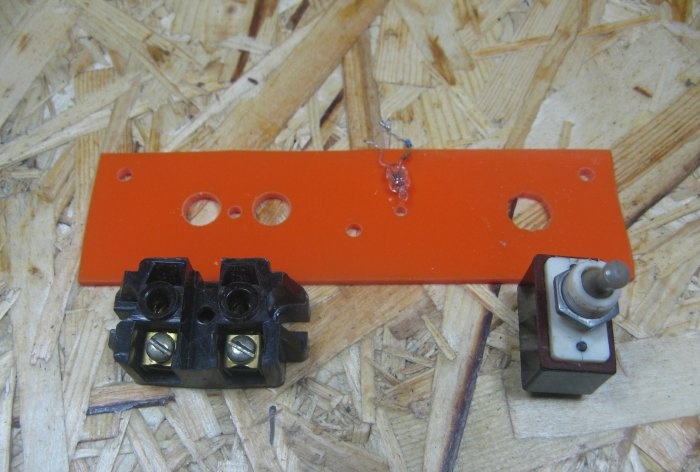
I'll make the front panel out of plastic. I'll use some orange plexiglas scraps that I had in stock.
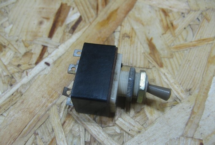
The switch will be toggle switch T3. You can use any current from two amperes.
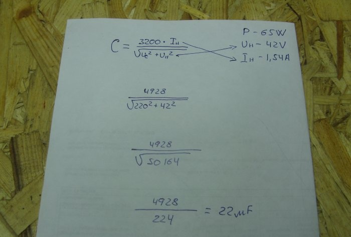
We calculate the quenching capacitor using a simple formula. My soldering iron has the following parameters:
The piece of paper shows a detailed calculation of the capacitor capacity. It turns out. we need a capacitor with a capacity of 22 mF.
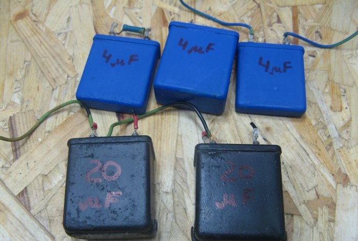
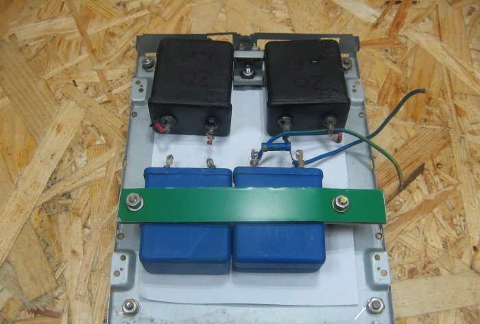
I took old capacitors, they were in the old soldering iron power supply housing. I sanded and painted them. Blue capacitors are 4 mF each, two capacitors are 20 mF each. The operating voltage of the capacitors must be at least 350 Volts. Those that are 4 uF, I have for 450 and 600 volts. Those that are 20 mF each are 200 volts, so I’ll turn them on in series. At the output we get a capacitance of 10 μF with an operating voltage of 400 volts. A 470 kΩ discharge resistor is soldered onto one of the capacitors. When disconnected from the network, it discharges the charge of the capacitors.
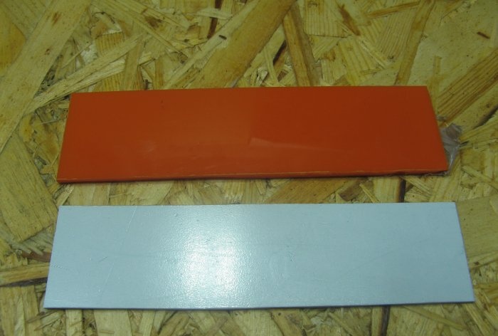
We cut out plugs for the body. The orange one is the front one, it's made of plexiglas.
The white plug is the back one, it is made of PVC plastic.
I'll spray paint the DVD drive housing.
On the plexiglas panel I make markings for: a socket, a toggle switch and a neon lamp. The neon lamp can be replaced with an LED connected through a resistor.
I secure the 4 mF capacitors with a bracket. Black capacitors, fastened together using a corner.
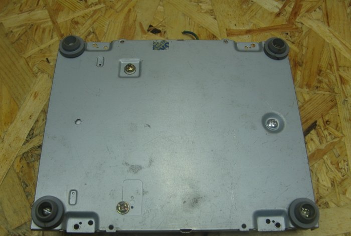
I screwed the legs on the bottom. In the role of legs, covers for medical vials.
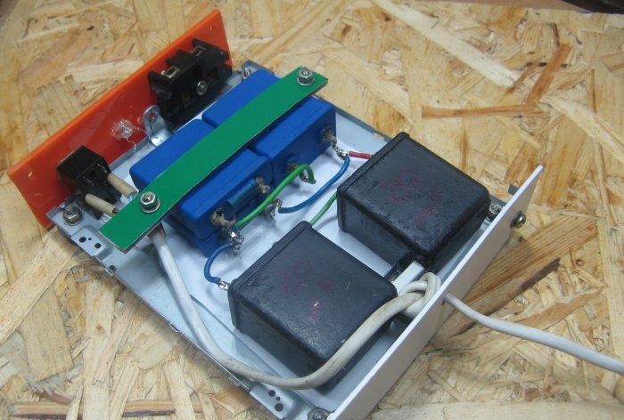
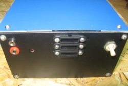
PVC back panel. I fastened it with screws and drilled a hole for the power cord. The capacitors were soldered in parallel. I solder the power cord to the toggle switch.
One of the network wires, through a toggle switch, goes to the socket. The second wire is through the capacitor to the socket. The neon lamp is connected from a toggle switch.
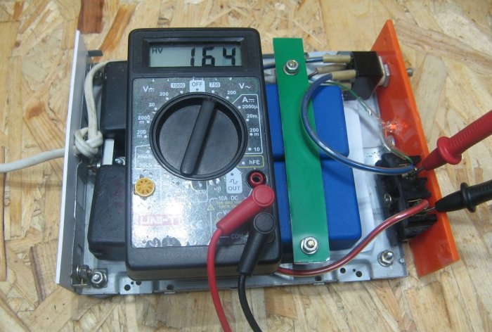
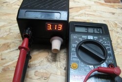
When turned on without load, the voltage is about 160 volts.
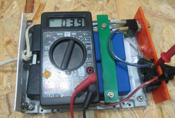
With a soldering iron connected, the voltage is about 40 volts.
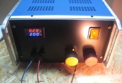
This is what the power supply turned out to be. Affordable and reliable. I've been using this method for a very long time. You can also calculate a capacitor for any low-voltage load.
Making a 42 V soldering iron attachment
The case for the power supply of the soldering iron will be the case from an old DVD drive. I'm thinking of painting it, apparently I'll have to leave the sticker, with a guide for the disk underneath it. Removing it creates a hole, which I don’t need.
I'll make the front panel out of plastic. I'll use some orange plexiglas scraps that I had in stock.
The switch will be toggle switch T3. You can use any current from two amperes.
We calculate the quenching capacitor using a simple formula. My soldering iron has the following parameters:
- - power 65 watts;
- - operating voltage 42 volts;
- - operating current 1.54 amperes.
The piece of paper shows a detailed calculation of the capacitor capacity. It turns out. we need a capacitor with a capacity of 22 mF.
I took old capacitors, they were in the old soldering iron power supply housing. I sanded and painted them. Blue capacitors are 4 mF each, two capacitors are 20 mF each. The operating voltage of the capacitors must be at least 350 Volts. Those that are 4 uF, I have for 450 and 600 volts. Those that are 20 mF each are 200 volts, so I’ll turn them on in series. At the output we get a capacitance of 10 μF with an operating voltage of 400 volts. A 470 kΩ discharge resistor is soldered onto one of the capacitors. When disconnected from the network, it discharges the charge of the capacitors.
We cut out plugs for the body. The orange one is the front one, it's made of plexiglas.
The white plug is the back one, it is made of PVC plastic.
I'll spray paint the DVD drive housing.
On the plexiglas panel I make markings for: a socket, a toggle switch and a neon lamp. The neon lamp can be replaced with an LED connected through a resistor.
I secure the 4 mF capacitors with a bracket. Black capacitors, fastened together using a corner.
I screwed the legs on the bottom. In the role of legs, covers for medical vials.
PVC back panel. I fastened it with screws and drilled a hole for the power cord. The capacitors were soldered in parallel. I solder the power cord to the toggle switch.
One of the network wires, through a toggle switch, goes to the socket. The second wire is through the capacitor to the socket. The neon lamp is connected from a toggle switch.
When turned on without load, the voltage is about 160 volts.
With a soldering iron connected, the voltage is about 40 volts.
This is what the power supply turned out to be. Affordable and reliable. I've been using this method for a very long time. You can also calculate a capacitor for any low-voltage load.
Watch the video
Similar master classes
Particularly interesting
Cable antenna for digital TV in 5 minutes
A selection of simple and effective schemes.
Three-phase voltage from single-phase in 5 minutes
Starting a three-phase motor from a single-phase network without a capacitor
Eternal flashlight without batteries
How to make an inexpensive but very powerful LED lamp
Comments (20)

