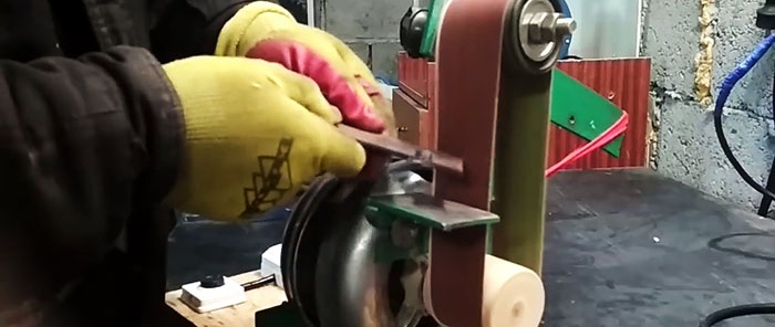
The simplest grinder without a lathe from a washing machine engine
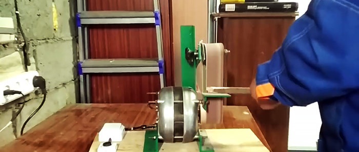
The engine from an old washing machine has enough power to assemble a quite convenient grinder on its basis. However, most of the existing schemes for such homemade machines involve turning and welding. If such equipment is not available, then you can assemble a small grinder with only a grinder and a drill.

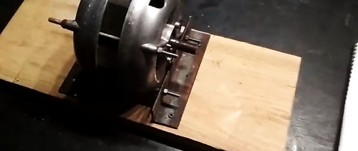
To make the engine mount, 2 corners of 30x30 mm are used. Holes are drilled into them for the studs coming out of the electric motor housing, after which the corners are screwed to the work table using self-tapping screws.
After mounting the motor, you should prepare it to turn on without capacitors. By using multimeter You need to test all the wires for resistance. To do this, the device is set to a resistance value of 200 Ohms.You need to ring the wires in pairs in different combinations. The pair that creates the greatest resistance is the starting winding, which must be marked with electrical tape. The remaining 2 wires are the working winding, their resistance will be almost 2 times less.
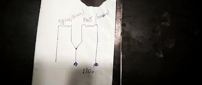
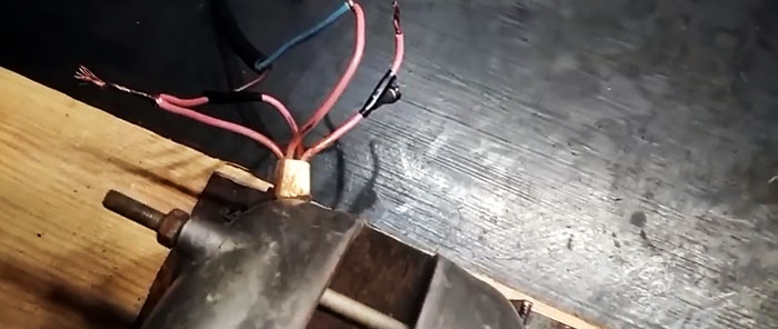
To start the motor without capacitors, you need to connect the wires according to the diagram suggested in the photo. Wiring from the working and starting windings is wound onto one power core. Only the remaining wiring of the working winding is connected to the second power core. After applying current, the motor shaft will begin to rotate, but very slowly. In order for it to gain normal speed, you will need to touch the free conductor starting winding to the supply wire for a split second. The engine will then return to normal operating mode. In the future, this circuit will be equipped with a switch.
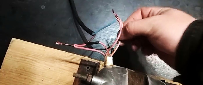
Next, a drive roller is installed on the motor shaft. You can simply drill a wooden cylinder the size of the sanding belt and place it on the shaft.
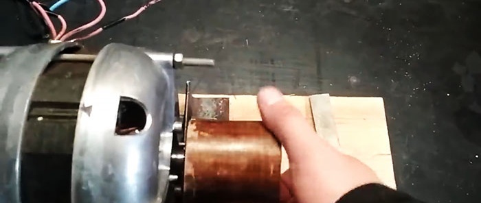
To center it, you need to make a temporary stop, as in the photo, and start the motor. With the engine running, the roller is ground with a chisel and sanded with sandpaper.
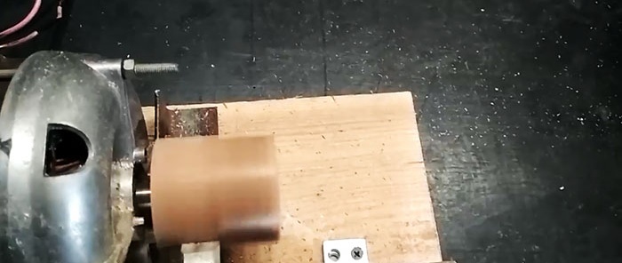
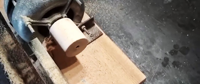
To securely fasten the roller, you need to make a countersunk hole in it and screw a self-tapping screw through it so that its end rests against the groove on the shaft.
The driven shaft of the grinder is made from two timing belt tension rollers, which is tightened with a long bolt with a ground head.
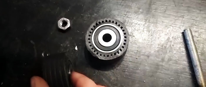
This, in turn, is passed through one of the doors of the door hinge before installing the rollers.
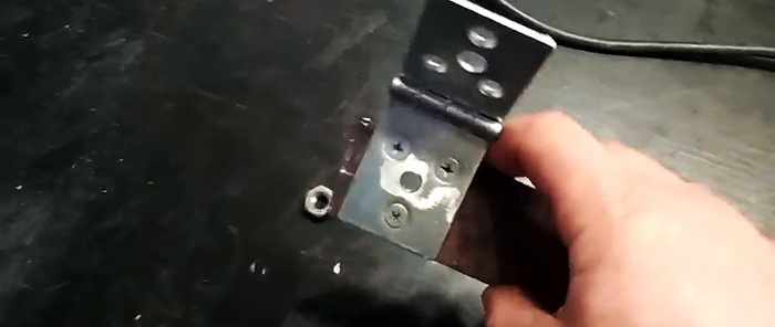
The second leaf is screwed with several screws onto the edge of the steel strip. A hole is made in the strip and an M8 thread is cut for the wing bolt.
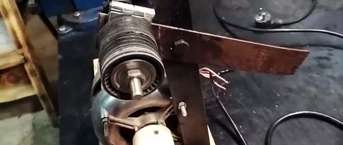
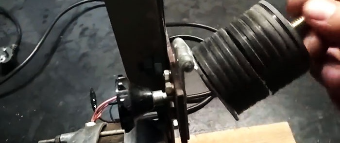
It is necessary that when the wing rotates, the bolt is screwed through the hole in the first sash and rests against the second with rollers, thereby changing the closing angle.
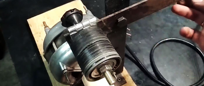
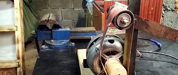
Next, through the mounting studs on the engine, you need to install a vertical stand from the strip. A hole is made in it to secure the tension arm with a loop and a roller. The drilling height is adjusted to the size of the sanding belt.
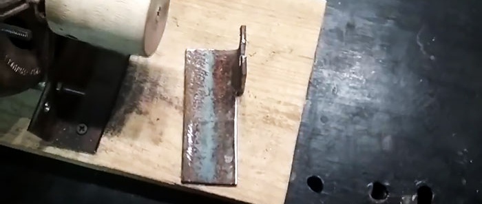
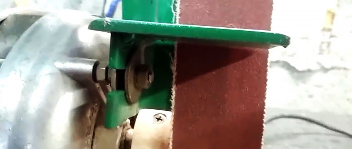
An internal stop is cut from a 50x50 mm corner to prevent the tape from being pulled back during grinding. This piece will attach to the top left stud on the engine.
The support table can be bent from the strip and attached to the same stud, or if possible, simply weld the plate to the existing internal stop holder.
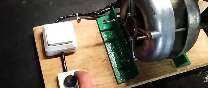
To use the machine safely, you need to install a light switch on it. He must break the power supply circuit of the working winding. In this case, the free wiring of the starting winding must be connected to the power supply through the bell button. In the future, to start the engine, you need to press the switch and momentarily press the bell button.
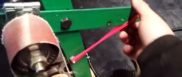
To tension the tape, an elastic band or spring is attached to the shoulder opposite the roller from the strip. At the bottom it can be hooked onto a protruding pin. To ensure that the belt does not come off the rollers during rotation, the wing bolt is adjusted. It changes the angle of inclination of the driven roller, preventing the possibility of derailment.
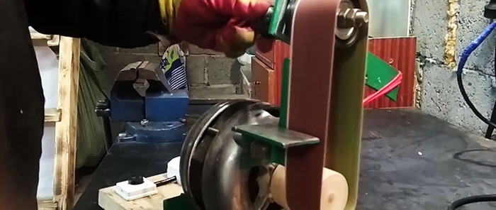
This design of the machine, with a sufficient length of the vertical stand, allows you to change the installation height of the tension mechanism, thereby adapting the grinder to different sanding belts. Its advantage is also its lightness and compactness.This grinder is primarily suitable for working with metal, since the engine is not protected from sawdust, of which a lot is produced when grinding wood.


Basic materials:
- electric motor from a washing machine;
- corner 30x30 mm;
- corner 50x50 mm;
- 2 timing belt tension rollers;
- steel strip 40 mm;
- door hinge;
- M8 bolt with wing;
- sanding belt;
- light switch;
- doorbell button;
- tension spring or rubber ring.

Grinder assembly
To make the engine mount, 2 corners of 30x30 mm are used. Holes are drilled into them for the studs coming out of the electric motor housing, after which the corners are screwed to the work table using self-tapping screws.

After mounting the motor, you should prepare it to turn on without capacitors. By using multimeter You need to test all the wires for resistance. To do this, the device is set to a resistance value of 200 Ohms.You need to ring the wires in pairs in different combinations. The pair that creates the greatest resistance is the starting winding, which must be marked with electrical tape. The remaining 2 wires are the working winding, their resistance will be almost 2 times less.


To start the motor without capacitors, you need to connect the wires according to the diagram suggested in the photo. Wiring from the working and starting windings is wound onto one power core. Only the remaining wiring of the working winding is connected to the second power core. After applying current, the motor shaft will begin to rotate, but very slowly. In order for it to gain normal speed, you will need to touch the free conductor starting winding to the supply wire for a split second. The engine will then return to normal operating mode. In the future, this circuit will be equipped with a switch.

Next, a drive roller is installed on the motor shaft. You can simply drill a wooden cylinder the size of the sanding belt and place it on the shaft.

To center it, you need to make a temporary stop, as in the photo, and start the motor. With the engine running, the roller is ground with a chisel and sanded with sandpaper.


To securely fasten the roller, you need to make a countersunk hole in it and screw a self-tapping screw through it so that its end rests against the groove on the shaft.
The driven shaft of the grinder is made from two timing belt tension rollers, which is tightened with a long bolt with a ground head.

This, in turn, is passed through one of the doors of the door hinge before installing the rollers.

The second leaf is screwed with several screws onto the edge of the steel strip. A hole is made in the strip and an M8 thread is cut for the wing bolt.


It is necessary that when the wing rotates, the bolt is screwed through the hole in the first sash and rests against the second with rollers, thereby changing the closing angle.


Next, through the mounting studs on the engine, you need to install a vertical stand from the strip. A hole is made in it to secure the tension arm with a loop and a roller. The drilling height is adjusted to the size of the sanding belt.

An internal stop is cut from a 50x50 mm corner to prevent the tape from being pulled back during grinding. This piece will attach to the top left stud on the engine.
The support table can be bent from the strip and attached to the same stud, or if possible, simply weld the plate to the existing internal stop holder.

To use the machine safely, you need to install a light switch on it. He must break the power supply circuit of the working winding. In this case, the free wiring of the starting winding must be connected to the power supply through the bell button. In the future, to start the engine, you need to press the switch and momentarily press the bell button.

To tension the tape, an elastic band or spring is attached to the shoulder opposite the roller from the strip. At the bottom it can be hooked onto a protruding pin. To ensure that the belt does not come off the rollers during rotation, the wing bolt is adjusted. It changes the angle of inclination of the driven roller, preventing the possibility of derailment.

This design of the machine, with a sufficient length of the vertical stand, allows you to change the installation height of the tension mechanism, thereby adapting the grinder to different sanding belts. Its advantage is also its lightness and compactness.This grinder is primarily suitable for working with metal, since the engine is not protected from sawdust, of which a lot is produced when grinding wood.


Watch the video
Similar master classes

Grinder from a washing machine engine

The simplest grinder without welding and turning from a washing machine engine
Sharpener from a washing machine engine
How to connect the motor from a washing machine to 220 V

Jigsaw from a compressor from a refrigerator
How to make a belt grinder without welding on the base
Particularly interesting
Comments (2)

