How to make a simple induction heater
An induction heater is a device that works using the magnetic properties of metals. Making it yourself is very simple. The device will be useful not only for studying the basics of electrical engineering, but also for practical purposes, for example, for hardening parts. After a little modification it can be used to assemble a home heater.
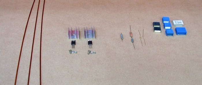
To assemble an induction heater we will need:
There are no strict requirements for details. Instead of those indicated, you can use any N-channel field devices with a similar pinout and a current of at least 10 A. The dissipation power of the input resistors R3 and R4 is 2 W, with a resistance spread of 100 - 620 Ohms.
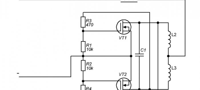
The induction heater circuit is shown below.
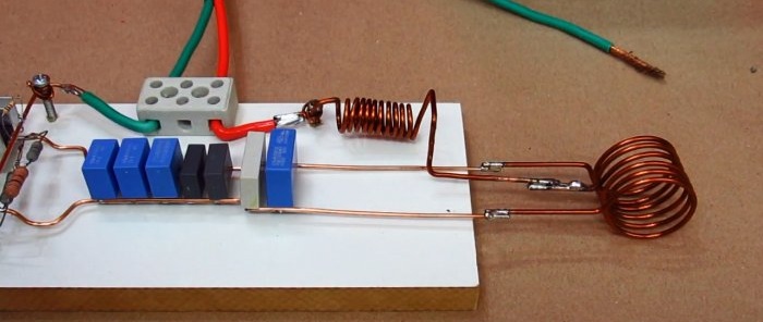
The circuit is quite simple, so we will assemble it using a hinged installation. We will subsequently fix all the elements on a small wooden block.
Let's prepare the details.If you don’t have resistors of the required values at hand, you can connect two in series.
Remember! When resistors are connected in series, their power remains unchanged. If you are replacing R3 or R4 with multiple resistors, make sure that all parts have the required power dissipation.
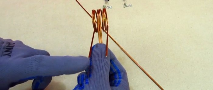
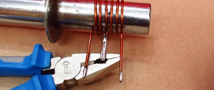
Let's make an inductor. On a smooth steel rod with a diameter of 70 mm, we wind 3 turns of copper wire, leaving straight sections at the ends for the terminals. You need to make two such coils.
We solder together two terminals of the coils, which form a common point.
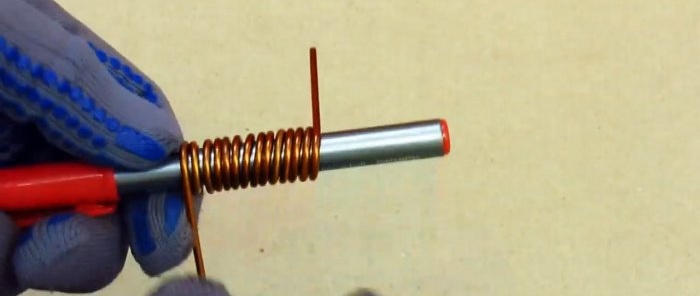
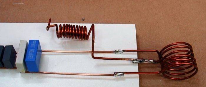
To make inductor L1, you need a thinner rod, with a diameter of 20-25 mm. Let's wind 10 turns of wire. For ease of installation, we will make sure that the terminals are located in opposite directions.
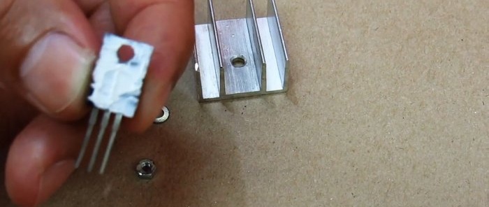
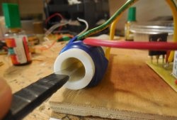
Let's install the transistors on the radiators, lubricating the inside of the case with thermal paste.
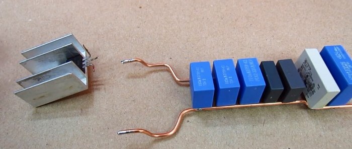
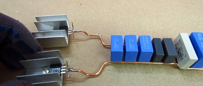
Let's assemble a capacitor bank of the required capacity by connecting them in parallel. As conductors we use the same copper wire that was used to wind the inductor.
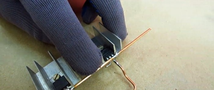
Let's shape the terminals of the transistors: carefully bend the leftmost leg to the left, and bend the rightmost leg forward.
Let's connect the central terminals of the transistors to a capacitor bank.
Let's connect the source of the first transistor (the rightmost terminal) to the source of the second with a jumper. Leave a small piece of wire for further installation.
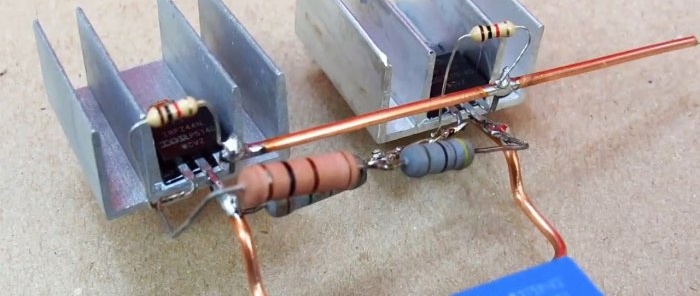
Solder the resistors according to the diagram.
On the other side of the capacitor bank we install an inductor, the middle terminal of which is connected to the inductor.
Let's install the power terminal block. The “positive” wire will go to the free end of the inductor, the “minus” wire will be connected to the jumper between the right legs of the transistors.
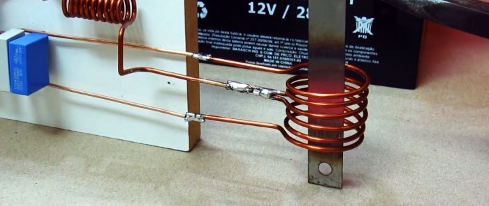
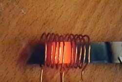
The device is ready for use. If you place a metal object in the inductor coil, it will quickly heat up.The coil itself will not heat up.
Required Parts
To assemble an induction heater we will need:
- copper wire with a diameter of 1-1.5 mm;
- 2 field-effect transistors IRF44N with radiators;
- a set of capacitors with a total capacity of 2-2.5 microfarads;
- 2 resistors with resistances of 10 Kom and 470 Ohm.
There are no strict requirements for details. Instead of those indicated, you can use any N-channel field devices with a similar pinout and a current of at least 10 A. The dissipation power of the input resistors R3 and R4 is 2 W, with a resistance spread of 100 - 620 Ohms.
The induction heater circuit is shown below.
Induction heater assembly process
The circuit is quite simple, so we will assemble it using a hinged installation. We will subsequently fix all the elements on a small wooden block.
Let's prepare the details.If you don’t have resistors of the required values at hand, you can connect two in series.
Remember! When resistors are connected in series, their power remains unchanged. If you are replacing R3 or R4 with multiple resistors, make sure that all parts have the required power dissipation.
Let's make an inductor. On a smooth steel rod with a diameter of 70 mm, we wind 3 turns of copper wire, leaving straight sections at the ends for the terminals. You need to make two such coils.
We solder together two terminals of the coils, which form a common point.
To make inductor L1, you need a thinner rod, with a diameter of 20-25 mm. Let's wind 10 turns of wire. For ease of installation, we will make sure that the terminals are located in opposite directions.
Let's install the transistors on the radiators, lubricating the inside of the case with thermal paste.
Let's assemble a capacitor bank of the required capacity by connecting them in parallel. As conductors we use the same copper wire that was used to wind the inductor.
Let's shape the terminals of the transistors: carefully bend the leftmost leg to the left, and bend the rightmost leg forward.
Let's connect the central terminals of the transistors to a capacitor bank.
Let's connect the source of the first transistor (the rightmost terminal) to the source of the second with a jumper. Leave a small piece of wire for further installation.
Solder the resistors according to the diagram.
On the other side of the capacitor bank we install an inductor, the middle terminal of which is connected to the inductor.
Let's install the power terminal block. The “positive” wire will go to the free end of the inductor, the “minus” wire will be connected to the jumper between the right legs of the transistors.
The device is ready for use. If you place a metal object in the inductor coil, it will quickly heat up.The coil itself will not heat up.
Watch the video
Similar master classes
Particularly interesting
Cable antenna for digital TV in 5 minutes
A selection of simple and effective schemes.
Three-phase voltage from single-phase in 5 minutes
Starting a three-phase motor from a single-phase network without a capacitor
Eternal flashlight without batteries
How to make an inexpensive but very powerful LED lamp
Comments (10)

