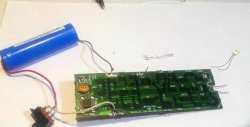
The simplest DIY radio transmitter and receiver in the world
When studying the nature of various physical phenomena and processes, it is interesting to conduct visual experiments. One such experiment is a demonstration of the operation of a simple radio transmitter and receiver. You can make such equipment yourself.
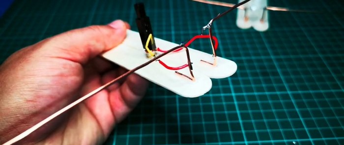
The radio transmitter consists of a wooden base onto which 2 wire conductors are glued with hot glue. Their horizontal length is 20 cm + 5 cm for the leg and fastening. The conductors must be bent at a right angle so that they rise above the sole at a height of 3 cm. The distance between the halves of the antenna must be at least 2 cm. One wire is supplied to each conductor from a piezoelectric element glued to the sole. At the bend, a short piece of thin wire without insulation is soldered to the antennas. Their edges are brought together so that when you press the piezoelectric element, a spark breaks between them.
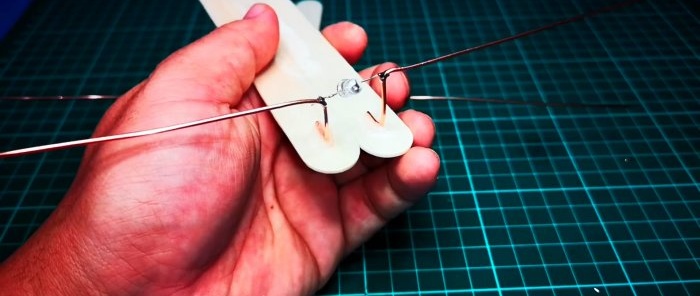
The radio receiver is a similar antenna on a wooden base.Only between its halves is soldered Light-emitting diode.
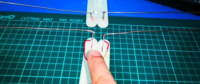
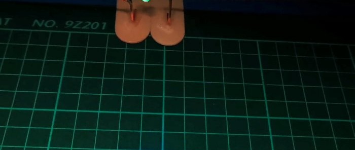
When you press the piezoelectric element of the transmitter, the created charge will generate a weak radio wave at the antenna. If you place the devices opposite each other at a distance of 5-10 cm, the receiver will react to it. This will be accompanied by a short-term sunburn LED.
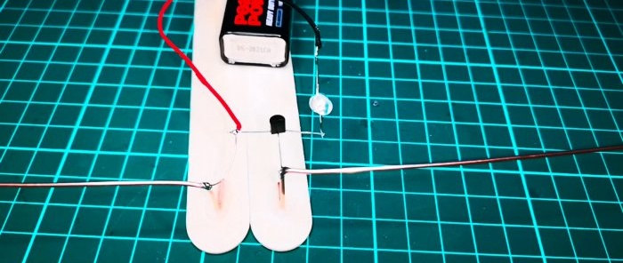
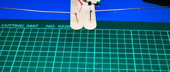
To increase the sensitivity of the receiver, a BC547 transistor is used. Its collector is soldered to one conductor of the antenna and the wire from the battery, the base to the second half of the antenna, and the emitter through Light-emitting diode to the remaining wiring from the crown.
With such an amplifier, the receiver will be able to respond already at a distance of 30-40 cm from the transmitter.
Materials:
- wire;
- wooden slats or bars;
- piezoelectric element from a lighter;
- Light-emitting diode;
- transistor BC547;
- crown battery.
Manufacturing process of radio receiver and transmitter
The radio transmitter consists of a wooden base onto which 2 wire conductors are glued with hot glue. Their horizontal length is 20 cm + 5 cm for the leg and fastening. The conductors must be bent at a right angle so that they rise above the sole at a height of 3 cm. The distance between the halves of the antenna must be at least 2 cm. One wire is supplied to each conductor from a piezoelectric element glued to the sole. At the bend, a short piece of thin wire without insulation is soldered to the antennas. Their edges are brought together so that when you press the piezoelectric element, a spark breaks between them.
The radio receiver is a similar antenna on a wooden base.Only between its halves is soldered Light-emitting diode.
When you press the piezoelectric element of the transmitter, the created charge will generate a weak radio wave at the antenna. If you place the devices opposite each other at a distance of 5-10 cm, the receiver will react to it. This will be accompanied by a short-term sunburn LED.
To increase the sensitivity of the receiver, a BC547 transistor is used. Its collector is soldered to one conductor of the antenna and the wire from the battery, the base to the second half of the antenna, and the emitter through Light-emitting diode to the remaining wiring from the crown.
With such an amplifier, the receiver will be able to respond already at a distance of 30-40 cm from the transmitter.
Watch the video
Similar master classes
How to make a high-speed engine from a bolt and nut

Contactless key

How to accurately determine the diameter of a thin wire or fishing line without a micrometer

How to build a simple converter using one transistor

How to make lever shears for cutting twigs and
How to make a simple 220V generator with your own hands
Particularly interesting
Comments (1)

