Adjustable computer cooling system
I offer a computer fan control system that is easy to manufacture and easy to use.
The system has 3 positions:
- disabled;
- low noise mode;
- maximum mode.
First, let's install additional fenestrons under the HDD.
To reduce noise, we attach the fenestrons to an elastic suspension.
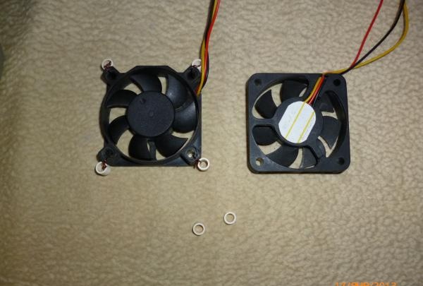
I used rubber rings and guy wires (all in a hurry)
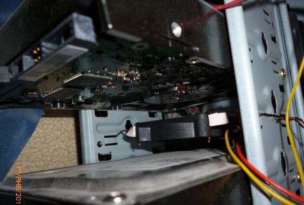
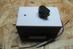
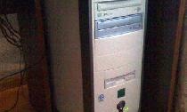
To control the cooling, I had to ruin the front plug:
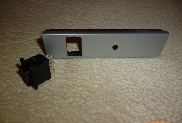
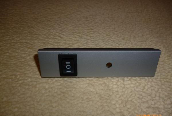
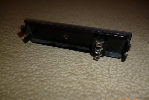
Insert the switch into the holes made and Light-emitting diode to indicate the operating mode.
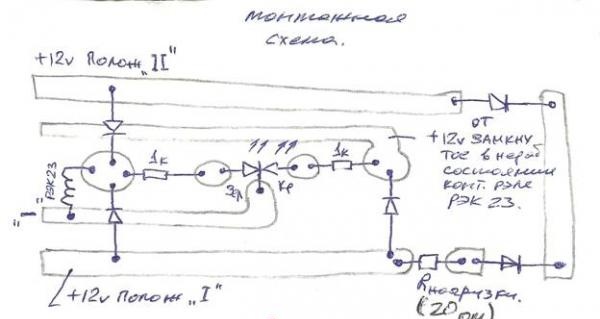
Now about the filling.
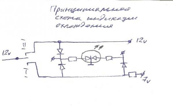
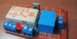
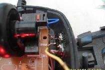
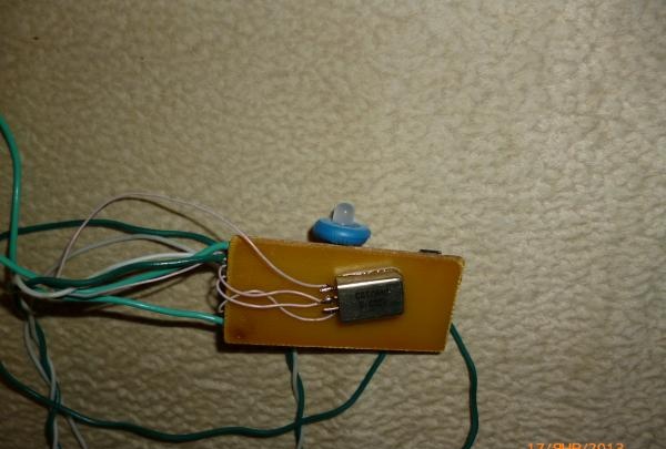
The diagram is presented in drawings and photos.
The circuit is not critical to the choice of radioelements:
- 1 kOhm resistors - any power (0.125 W mlt used);
- R load – a powerful resistor of at least 3 W (PEV-4 is used)
- Any diodes with a current of at least 0.5 A (1N4007 used)
- 2-position relay U power = 12 V (REK 23 (12V, 1A) was used)
- two-color Light-emitting diode.
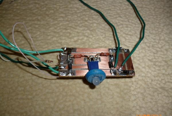
That's all.
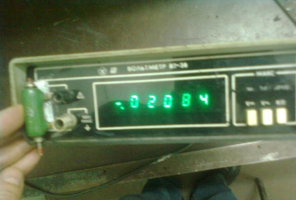
The only thing you have to adjust is the high-noise mode voltage.
In our case, the system controls three fenestrons, an input (120 mm) and two blowers for hard drives (60 mm). It was experimentally found that at a voltage of 7 Volts the noise is not great and the performance is acceptable. A wire rheostat was used to set the voltage to 7 Volts when the fenestrons were operating - a resistance of 20 Ohms was obtained.
In your case, the load resistance R may have to be adjusted.
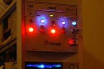
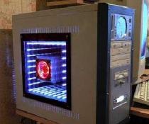
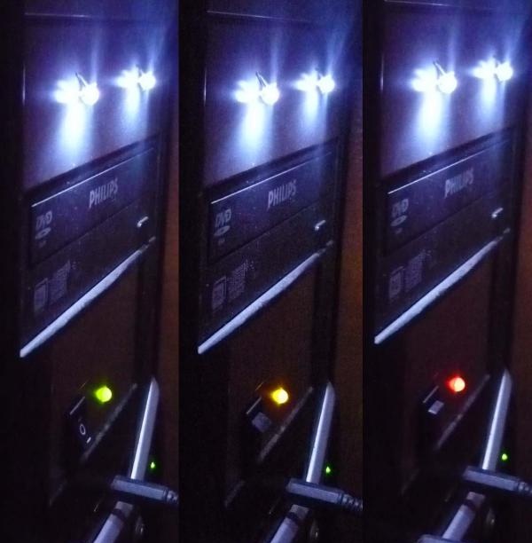
Here's what happened:
Switch Position:
0 - fenestrons are turned off (indicator color red);
I - low noise mode (indicator color yellow)
II - maximum mode (indicator color green)
The system has 3 positions:
- disabled;
- low noise mode;
- maximum mode.
First, let's install additional fenestrons under the HDD.
To reduce noise, we attach the fenestrons to an elastic suspension.

I used rubber rings and guy wires (all in a hurry)

To control the cooling, I had to ruin the front plug:


Insert the switch into the holes made and Light-emitting diode to indicate the operating mode.

Now about the filling.

The diagram is presented in drawings and photos.
The circuit is not critical to the choice of radioelements:
- 1 kOhm resistors - any power (0.125 W mlt used);
- R load – a powerful resistor of at least 3 W (PEV-4 is used)
- Any diodes with a current of at least 0.5 A (1N4007 used)
- 2-position relay U power = 12 V (REK 23 (12V, 1A) was used)
- two-color Light-emitting diode.

That's all.
The only thing you have to adjust is the high-noise mode voltage.
In our case, the system controls three fenestrons, an input (120 mm) and two blowers for hard drives (60 mm). It was experimentally found that at a voltage of 7 Volts the noise is not great and the performance is acceptable. A wire rheostat was used to set the voltage to 7 Volts when the fenestrons were operating - a resistance of 20 Ohms was obtained.
In your case, the load resistance R may have to be adjusted.

Here's what happened:

Switch Position:
0 - fenestrons are turned off (indicator color red);
I - low noise mode (indicator color yellow)
II - maximum mode (indicator color green)

Author crafts: Ika_tander
Similar master classes
Particularly interesting
Comments (7)

