How to make a universal puller from a hydraulic jack
A universal puller for disassembling connections with guaranteed tension (pulleys, bearings, bushings, etc.) will come in handy in a home workshop. You can make it from a bottle-type hydraulic jack, spending a little time and effort.
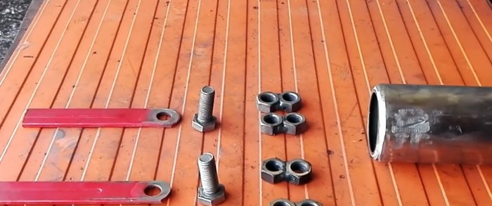
To make a homemade product, in addition to the jack, we will prepare the following materials and products:
To work you will need: vice, tape measure and marker, adjustable wrench, hammer, welding, grinder, etc.
We remove the plug from the filler hole, open the shut-off needle and drain the oil from the jack cavity into a separate container. At the same time, we move the working plunger up and down several times to increase oil drainage.
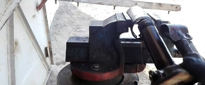
Clamping the jack in a vice, using an adjustable wrench, grabbing the hex nut, we tear off the housing head and, when it gives in, unscrew it by hand along with the working plunger and the retractable screw.
Then, lightly hitting the base of the housing with a hammer, we separate it along with the working plunger cylinder and the boost pump.
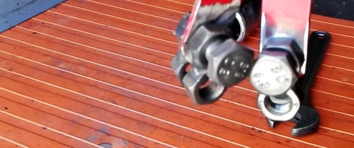
We weld the nuts in pairs, pressing them together with one of the six edges until we get 4 pairs. We mark a steel strip with holes at the ends and divide it into halves with a grinder.
We grind the paired nuts, smoothing the welds, as well as the halves of the steel strip with holes and the jack body.
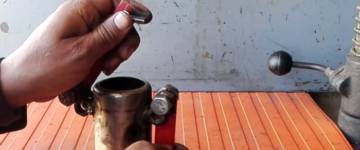
We assemble two identical units in the following order: screw one of the paired nuts onto the bolt, put on half of the strip using the hole, and screw the second pair of nuts.
We mark the body from the top on the outside with some indentation from the end using a ruler, a corner and a marker for welding above the assembled units at diametrically opposite points.
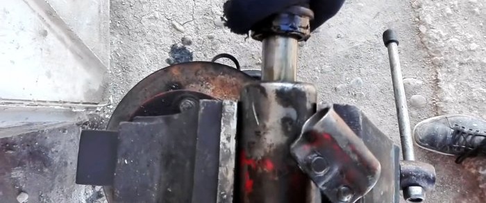
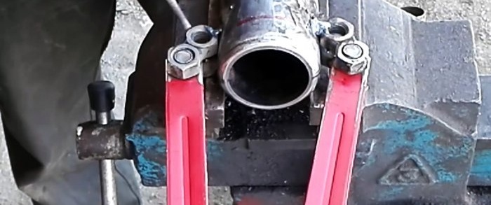
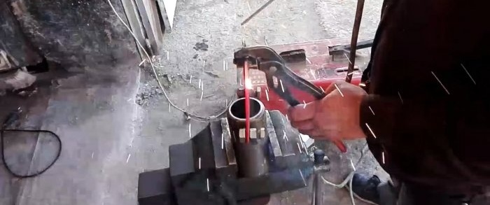
We fix the body in a vice and weld the units according to the markings so that their parts with levers do not come into contact with the cylindrical surface of the body.
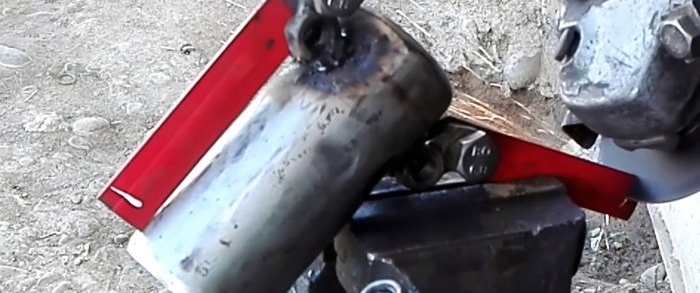
At the free ends of the arms, with a slight indentation from the edge, we use a grinder to cut grooves at an angle with a depth equal to two-thirds of the width of the strip and directed inward.
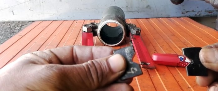
In two rectangular plates of the same size in the center of the long edge, we cut out V-shaped grooves with a grinder, and cover one side with a notch using a grinder.
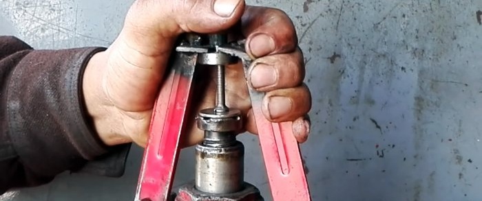
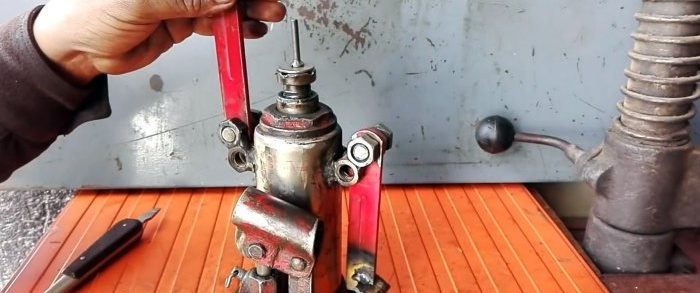
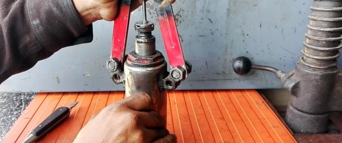
Then we insert them into the slots of the levers with the notch down and the grooves outward, and weld them in this position. If the levers are now turned and brought together, the V-shaped grooves of the plates form a square or diamond-shaped hole.
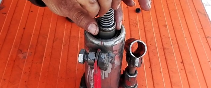
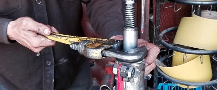
We assemble the jack in the reverse order of disassembly.We tighten the housing head with an adjustable wrench, checking the integrity and correct installation of the upper and lower o-rings.
We slightly open the shut-off needle and fill the required volume of A.T.F Dexron II transmission fluid or I20A spindle oil through the filling hole in the housing. We close the filling hole with a stopper.
First, we check the operation of the puller for lifting and lowering “idle”, then - in “in use”. The pressed bearing must be removed from the armature shaft of the electric motor.
We adjust the lift of the retractable screw. We place a steel nickel (coin) on its head and place the screw with the flat head down. We wrap the lever plates around the shaft on top of the bearing and activate the boost pump.
When the screw rests against the end of the shaft, and the bearing rests against the lever plates, it will begin, as the working plunger rises, to come off the shaft until it comes off completely. In the same way, we disassemble the tension connection between the shaft and gear.
Will need
To make a homemade product, in addition to the jack, we will prepare the following materials and products:
- bolts and nuts;
- steel strip with holes at the ends;
- metal plates;
- A.T.F Dexron II gear oil (or spindle I20A);
- a steel nickel (or quarter) and a flat head screw.
To work you will need: vice, tape measure and marker, adjustable wrench, hammer, welding, grinder, etc.
Puller manufacturing process
We remove the plug from the filler hole, open the shut-off needle and drain the oil from the jack cavity into a separate container. At the same time, we move the working plunger up and down several times to increase oil drainage.
Clamping the jack in a vice, using an adjustable wrench, grabbing the hex nut, we tear off the housing head and, when it gives in, unscrew it by hand along with the working plunger and the retractable screw.
Then, lightly hitting the base of the housing with a hammer, we separate it along with the working plunger cylinder and the boost pump.
We weld the nuts in pairs, pressing them together with one of the six edges until we get 4 pairs. We mark a steel strip with holes at the ends and divide it into halves with a grinder.
We grind the paired nuts, smoothing the welds, as well as the halves of the steel strip with holes and the jack body.
We assemble two identical units in the following order: screw one of the paired nuts onto the bolt, put on half of the strip using the hole, and screw the second pair of nuts.
We mark the body from the top on the outside with some indentation from the end using a ruler, a corner and a marker for welding above the assembled units at diametrically opposite points.
We fix the body in a vice and weld the units according to the markings so that their parts with levers do not come into contact with the cylindrical surface of the body.
At the free ends of the arms, with a slight indentation from the edge, we use a grinder to cut grooves at an angle with a depth equal to two-thirds of the width of the strip and directed inward.
In two rectangular plates of the same size in the center of the long edge, we cut out V-shaped grooves with a grinder, and cover one side with a notch using a grinder.
Then we insert them into the slots of the levers with the notch down and the grooves outward, and weld them in this position. If the levers are now turned and brought together, the V-shaped grooves of the plates form a square or diamond-shaped hole.
We assemble the jack in the reverse order of disassembly.We tighten the housing head with an adjustable wrench, checking the integrity and correct installation of the upper and lower o-rings.
We slightly open the shut-off needle and fill the required volume of A.T.F Dexron II transmission fluid or I20A spindle oil through the filling hole in the housing. We close the filling hole with a stopper.
First, we check the operation of the puller for lifting and lowering “idle”, then - in “in use”. The pressed bearing must be removed from the armature shaft of the electric motor.
We adjust the lift of the retractable screw. We place a steel nickel (coin) on its head and place the screw with the flat head down. We wrap the lever plates around the shaft on top of the bearing and activate the boost pump.
When the screw rests against the end of the shaft, and the bearing rests against the lever plates, it will begin, as the working plunger rises, to come off the shaft until it comes off completely. In the same way, we disassemble the tension connection between the shaft and gear.
Watch the video
Similar master classes
Particularly interesting
Comments (1)

