Do-it-yourself electric grinder file from a grinder
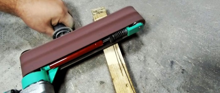
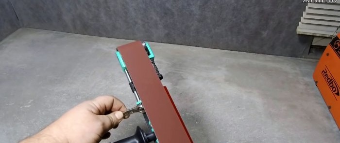
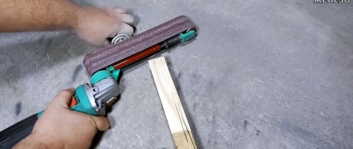
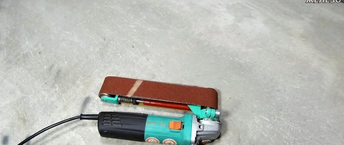
For on-site grinding work, you can make simple, but very reliable and productive equipment for an angle grinder. It can replace an electric file and a belt grinder.
Basic materials:
- sheet steel or strip 6 mm;
- profile pipes 15x15 mm and 20x20 mm;
- pipe 50 mm;
- gas lift 8 kg;
- spring;
- bearings 37x12x12 mm;
- bolts, nuts, washers;
- tape 610x100 mm;
Manufacturing process of an electric file grinder
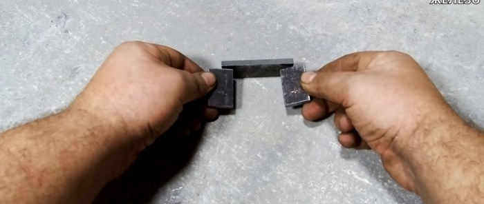
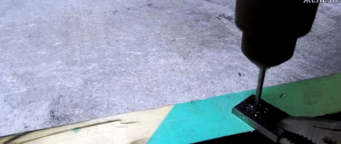
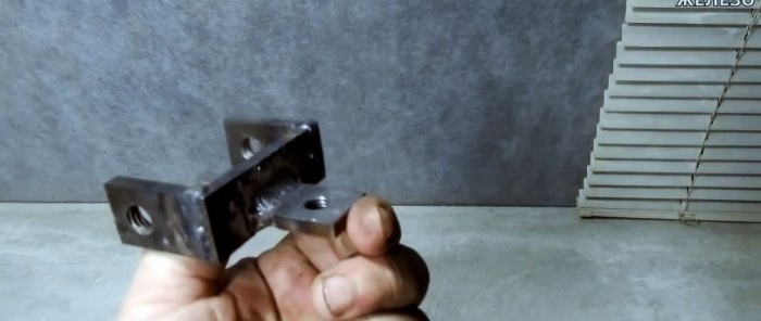
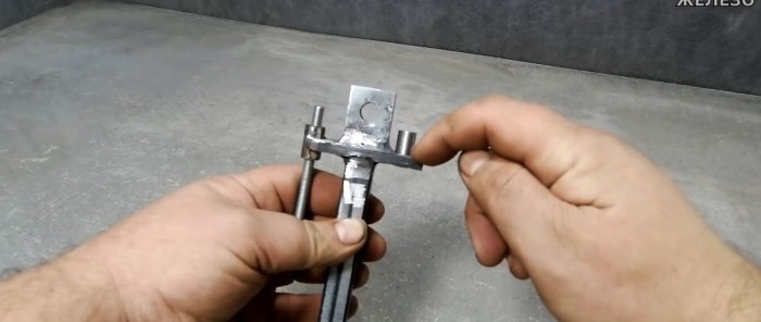
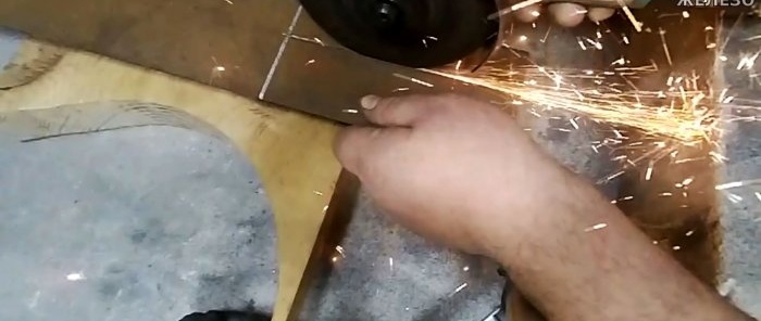
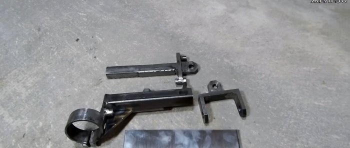
A 22 mm wide strip is cut from 6 mm steel to make the driven roller axis bracket. Its width is made arbitrary 50-70 mm depending on the selected type of tape. The height when using the recommended bearings should be 41 mm. Holes are drilled on the sides of the bracket and an M10 thread is cut to install the axle. An eye made of a strip with a hole and M12 thread is welded to it.
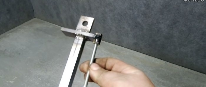
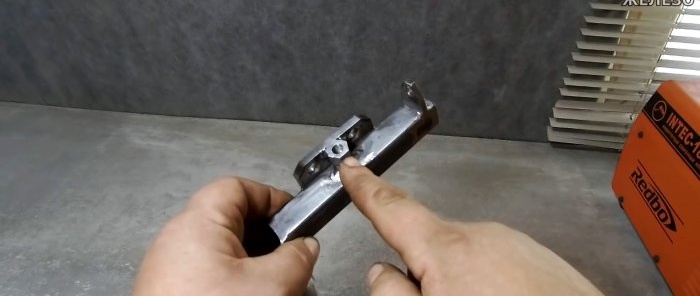
Next, a rod is made from a 15x15 mm profile pipe with a length of 123 mm. A small piece of strip of arbitrary length with a cut at the edge is welded perpendicularly to its end. Weld an extended M6 nut into it parallel to the pipe. An eye with a 12 mm hole is welded to the cross member. A long M6 bolt is screwed into the nut.
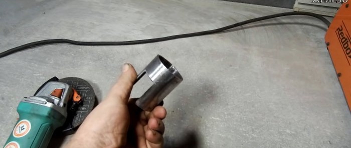
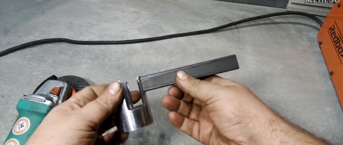
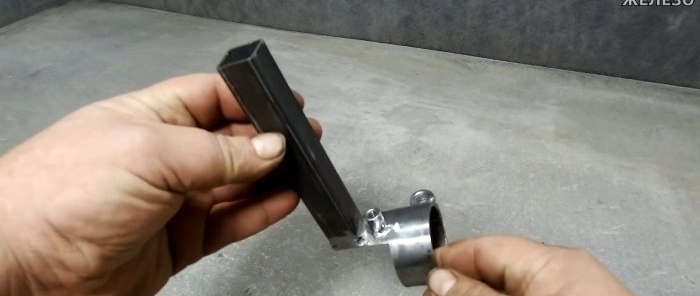
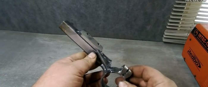
A 50 mm piece of pipe is used to attach it to an angle grinder in the form of a clamp. The workpiece is cut lengthwise and nuts are welded to it to tighten it. A piece of pipe 20x20 mm with a length of 128 mm is welded to the clamp. Half of the extended M6 nut is welded under it.
A cylinder made from a ground off extended M6 nut is welded to the transverse plate on the rod. Several thin sheet steel plates need to be welded onto the 15x15 mm tube itself so that it fits into the 20x20 mm guide without play.
A plate for support 52x170 mm is cut from 6 mm steel. 2 installation holes with M8 threads are drilled into it. A fastening for the plate, a travel stop and a nut are welded onto the guide with a clamp. The pipe itself is additionally secured to the clamp with a gusset.
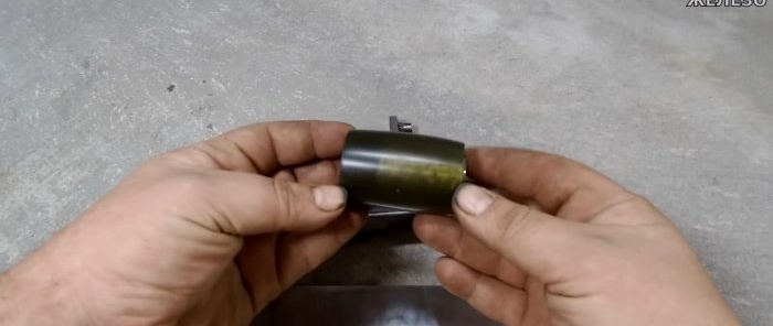
You also need to machine a barrel-shaped drive roller with a pressed or cut M14 thread so that it can be screwed onto the angle grinder spindle. Its width is 60 mm, diameter 35-37 mm.
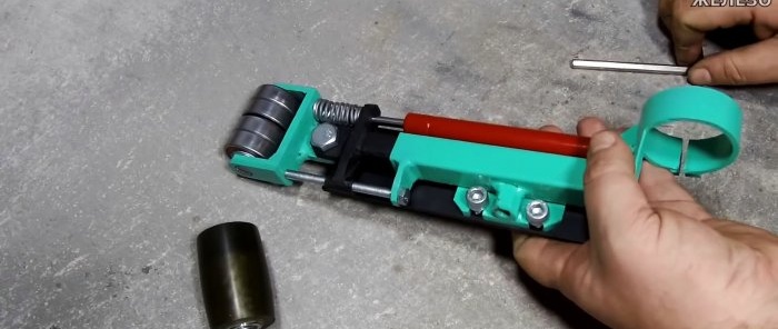
A bolt with a cut off head and slots for a screwdriver is inserted into the bracket. It has 4 bearings with washers between them. The result is a driven roller.
The bracket is connected to the rod, a spring is inserted between them, and a long M6 bolt is screwed into the opposite side. Next, a gas lift is installed. A support plate is screwed onto the rod mount.
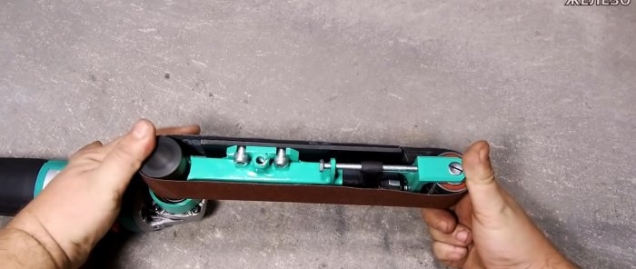
The clamp is clamped onto the grinder instead of the casing. The drive roller is screwed onto its spindle. Then a 610x100 mm sanding belt is stretched, divided in half lengthwise. A standard handle from an angle grinder is screwed into the nut near the support.
By rotating the long M6 bolt, you can adjust the position of the tape on the roller so that it does not fly off. Due to the gas lift, it has good tension, so it does not slip during operation. Thus, at the end we have an elegant tool with a high grinding speed.
Watch the video
Similar master classes
How to make a grinder attachment for an angle grinder

The simplest grinder made from a grinder, a bicycle hub and a roller
Do-it-yourself miter saw based on a grinder with a broach
How to make a belt grinder without welding on the base
You are unlikely to see a more functional grinder machine
How to make a powerful machine from old drums and hubs
Particularly interesting
Comments (0)

